RFID tag reader with tag location indicated by visible light beam

Inactive Publication Date: 2005-09-29
STEINBERG DAN ALAN
View PDF8 Cites 131 Cited by
  • Summary
  • Abstract
  • Description
  • Claims
  • Application Information

AI Technical Summary

Problems solved by technology

A problem with RFID tags is determining where the tag is located relative to the RFID reader device.
This can cause confusion for the user when there are many RFID tags present, or when the user wants to scan for tags in a localized area, or

Method used


Image

  • RFID tag reader with tag location indicated by visible light beam
  • RFID tag reader with tag location indicated by visible light beam
  • RFID tag reader with tag location indicated by visible light beam

Examples


Embodiment Construction

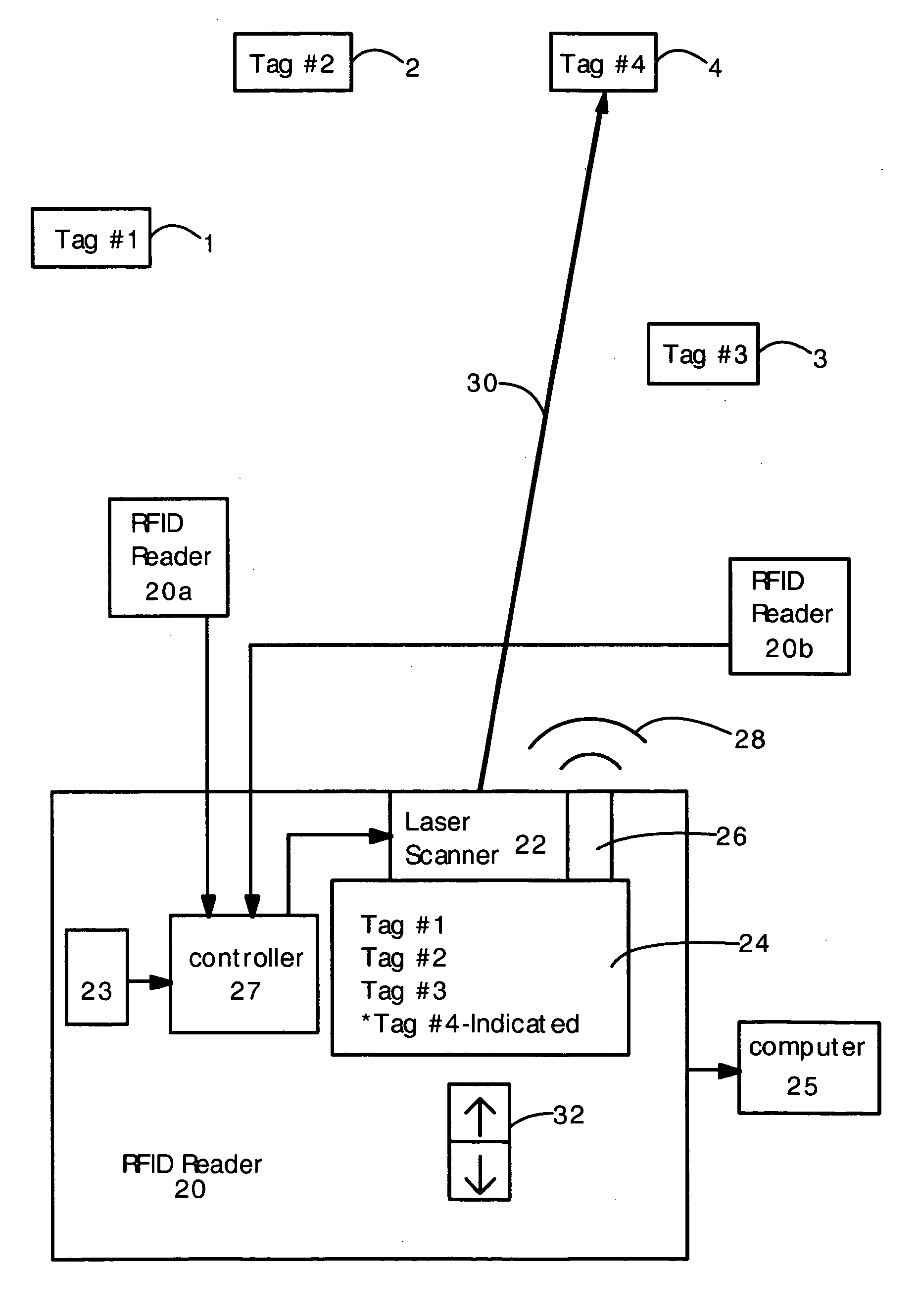
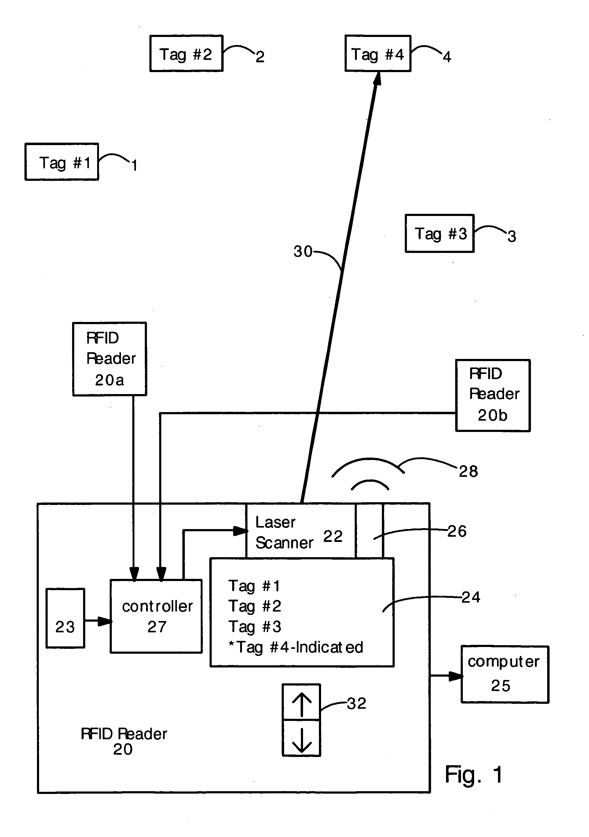
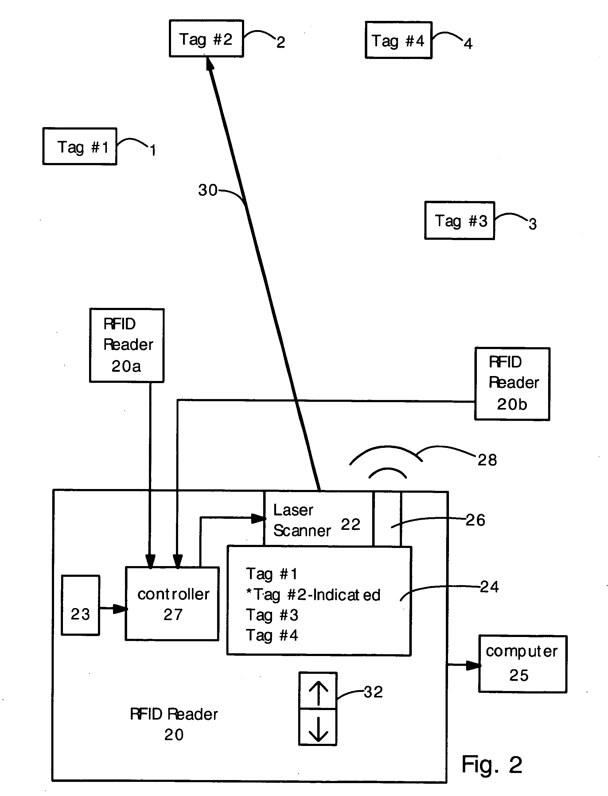
[0015] The present invention provides an RFID tag reader that uses a light beam to indicate the physical location of a tag, or indicate the volume of physical space that the RFID reader is scanning. In a first embodiment, the RFID reader electronically determines the location of the RFID tag (e.g. by sharing and combining location data with a plurality of other RFID tag readers or antennas). Then, using this data, the RFID reader controls a laser scanner to direct a visible laser beam at the tag, so that a user can see where the tag is located. If several tags have been detected, then the user can select which tag the RFID reader will illuminate with the laser. In the second embodiment, the RFID reader emits a narrow interrogating RF beam, and a laser beam or light beam is oriented and dimensioned (i.e. the solid angle size is adjusted) to substantially overlap the RF beam. The RFID reader can only read tags located within the interrogating RF beam, and the light beam visually indic...


PUM


Abstract

Provided are radiofrequency identification (RFID) tag readers having visible light beams to visually indicate the location of an RFID tag. In one embodiment, the RFID reader can electronically determine the location of an RFID tag. The RFID reader has a visible laser scanner that is controlled to target the RFID tag, based on the electronic location data. Hence, the user will see a laser beam point toward the RFID tag location. In another embodiment, the RFID tag reader has a directional RF interrogating beam, and a visible light beam that overlaps with the RF interrogating beam. The visible light beam indicates the volume of space where the RFID tag reader can detect RFID tags. The size of the visible light beam can be adjusted to be bigger for more sensitive tags (e.g. active tags) or smaller for less sensitive tags. (e.g. passive tags), or adjusted for RF output power.

Description

RELATED APPLICATIONS [0001] The present application claims the benefit of priority from copending provisional application No. 60 / 556,044, filed on Mar. 24, 2004.FIELD OF THE INVENTION [0002] The present invention relates generally to radio frequency identification (RFID) tag readers. More particularly, it relates to an RFID tag reader that uses a light beam to indicate the location of an RFID tag, or indicate where the RFID reader is projecting an interrogating RF beam. BACKGROUND OF THE INVENTION [0003] Radiofrequency identification (RFID) tags are well known in the art. RFID tags are small electronic circuits that respond with a data-carrying RF reply signal when interrogated with an RF signal at a particular frequency. Tags are either passive or active. Passive tags rely on the energy of the interrogation signal to generate the reply signal; active tags carry their own battery. Active tags have a much longer range than active tags. Active tags typically can be queried up to about...

Claims


Application Information

Patent Timeline
IPC IPC(8): G06K7/08G06K17/00G08B13/14
CPCG06K7/10079G06K2017/0045G06K7/10336
Inventor STEINBERG, DAN ALAN
Owner STEINBERG DAN ALAN
Why Eureka
Try Eureka