Display device and method for determining an area of importance in an original image

Inactive Publication Date: 2005-09-29
MONUMENT PEAK VENTURES LLC
View PDF23 Cites 93 Cited by
  • Summary
  • Abstract
  • Description
  • Claims
  • Application Information

AI Technical Summary

Problems solved by technology

However, photographers typically make area of importance designations using such tools only on selected images during the post capture phase.
However, some consumers prefer not to use eye monitoring systems.

Method used


Image

  • Display device and method for determining an area of importance in an original image
  • Display device and method for determining an area of importance in an original image
  • Display device and method for determining an area of importance in an original image

Examples


Embodiment Construction

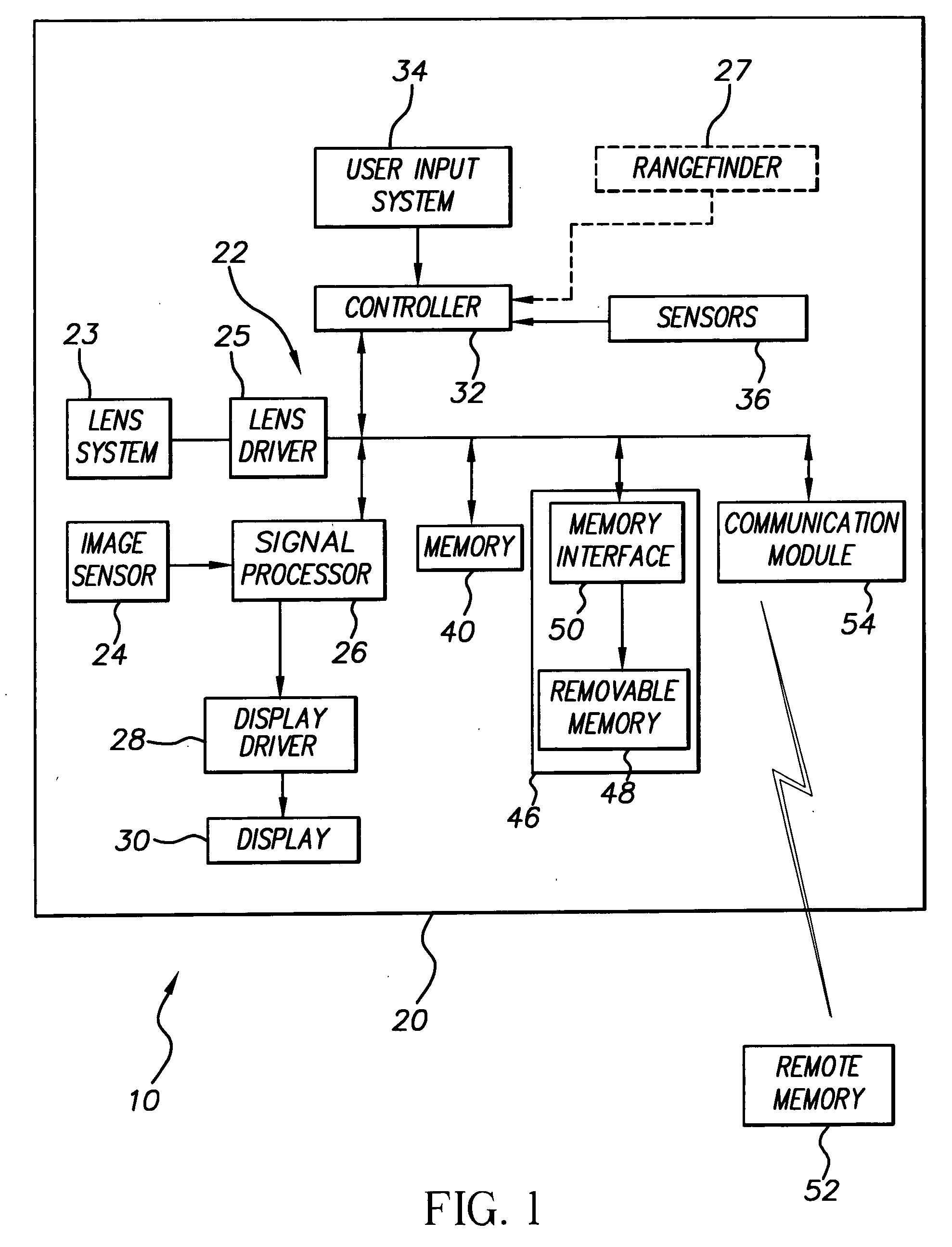
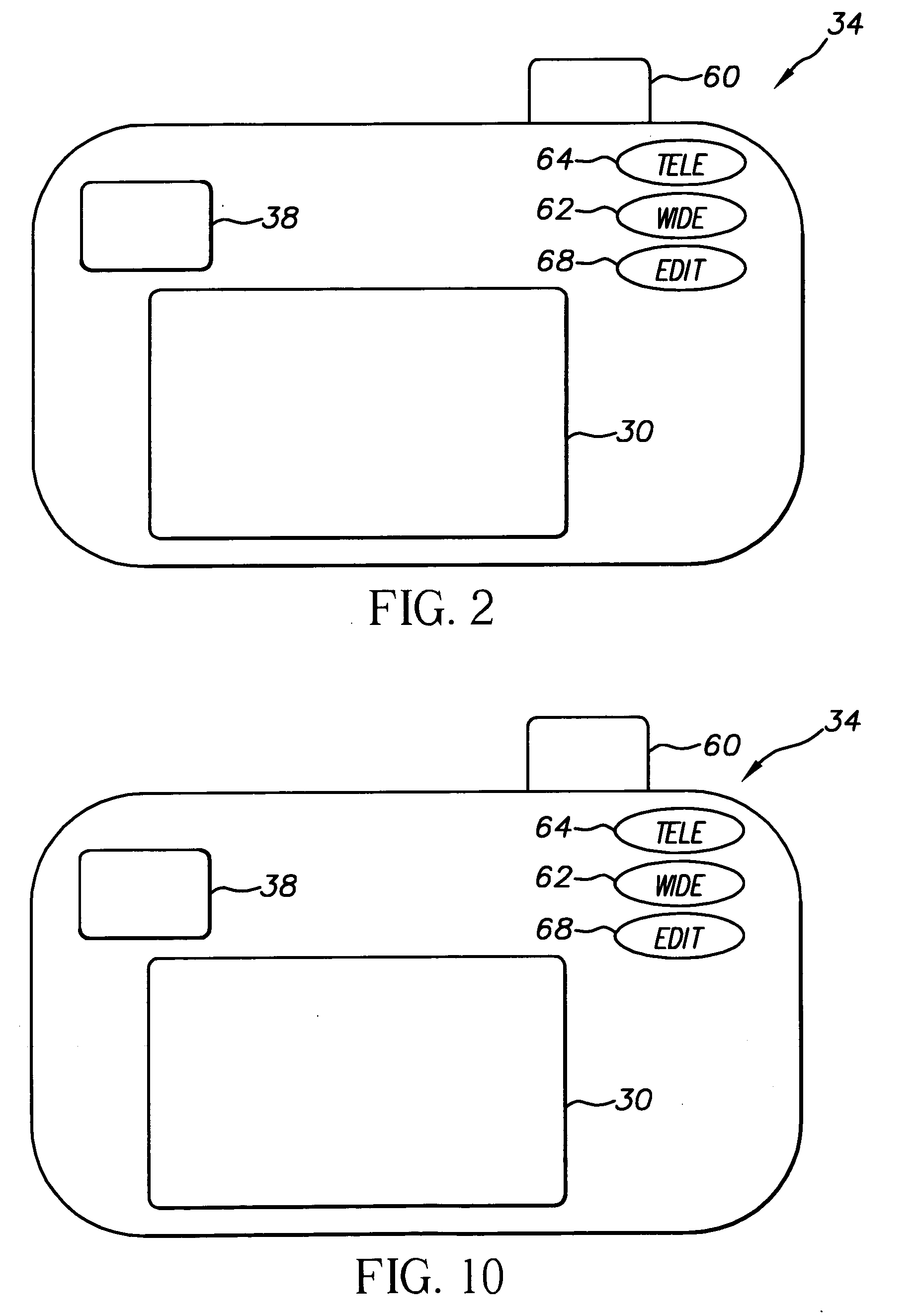
[0039]FIG. 1 shows a block diagram of an embodiment of a display device 10. FIG. 2 shows a back, elevation view of the display device 10 of FIG. 1. As is shown in FIGS. 1 and 2, display device 10 takes the form of a digital camera 12 comprising a body 20 containing an image capture system 22 having a lens system 23, an image sensor 24, a signal processor 26, an optional display driver 28 and a display 30. In operation, light from a scene is focused by lens system 23 to form an image on image sensor 24. Lens system 23 can have one or more elements.

[0040] Lens system 23 can be of a fixed focus type or can be manually or automatically adjustable. In the embodiment shown in FIG. 1, lens system 23 is automatically adjusted. Lens system 23 can be simple, such as having a single focal length with manual focusing or a fixed focus. In the example embodiment shown in FIG. 1, taking lens unit 22 is a motorized 6× zoom lens unit in which a mobile element or elements (not shown) are driven, rel...


PUM


Abstract

Display devices and methods for operating a display device are provided. A display device has a source of an original image and a display. A user input system is adapted to generate a non-directional signal in response to a user input action. A controller is provided and is adapted to detect the non-directional signal and to successively designate a different one of a set of portions of the original image in response to each non-directional signal. The controller is further adapted to cause the display to present a portion evaluation image showing the currently designated portion of the original image and to determine and area of importance in the original image based upon the currently designated portion. At least one of the portions of the set of portions of the original image is non-central with respect to the original image.

Description

CROSS-REFERENCE TO RELATED APPLICATIONS [0001] Reference is made to commonly assigned, co-pending U.S. Ser. No. 10 / 061,385, entitled SYSTEM AND METHOD OF PROCESSING A DIGITAL IMAGE FOR USER ASSESSMENT OF AN OUTPUT IMAGE PRODUCT, filed Feb. 1, 2002 in the name of John R. Randall, et al.; U.S. Ser. No. 10 / 745,006, entitled DISPLAY DEVICE WITH AUTOMATIC AREA OF IMPORTANCE DISPLAY, filed Dec. 23, 2003 in the name of Susan J. Beck; and U.S. Ser. No. 10 / 292,684, entitled CAMERA HAVING CONTINUOUSLY CROPPING VIEWFINDER, filed Nov. 12, 2002.FIELD OF THE INVENTION [0002] The present invention relates to imaging methods and systems that determine an area of importance in an original image. BACKGROUND OF THE INVENTION [0003] Digital images are becoming an increasingly popular form of info-imaging. One reason for this popularity is the ease with which users can manipulate, edit, alter and enhance such digital images after capture. For example, users often use manual digital imaging and editing t...

Claims


Application Information

Patent Timeline
Patent Type & Authority Applications(United States)
IPC IPC(8): G06T3/40G06T11/60
CPCG06T11/60H04N2101/00H04N5/23293H04N5/23229H04N23/80H04N23/635
Inventor CANNON, JAMES W.BELZ, STEVEN M.
Owner MONUMENT PEAK VENTURES LLC
Why Eureka
Try Eureka