Display driver and electronic instrument

Active Publication Date: 2005-09-29
SEIKO EPSON CORP
View PDF4 Cites 35 Cited by
  • Summary
  • Abstract
  • Description
  • Claims
  • Application Information

AI Technical Summary

Problems solved by technology

Since the calculation circuit simultaneously processes display data for 7 lines×480 columns read from a memory, the calculation circuit becomes complicated and the circuit area is increased.
Moreover, since the amount of display data is increased

Method used


Image

  • Display driver and electronic instrument
  • Display driver and electronic instrument
  • Display driver and electronic instrument

Examples


Example

[0049] The present invention has been achieved in view of the above-described technical problem and may provide a display driver and an electronic instrument having a small layout area, excelling in cost performance, and capable of maintaining high display quality of a display panel.

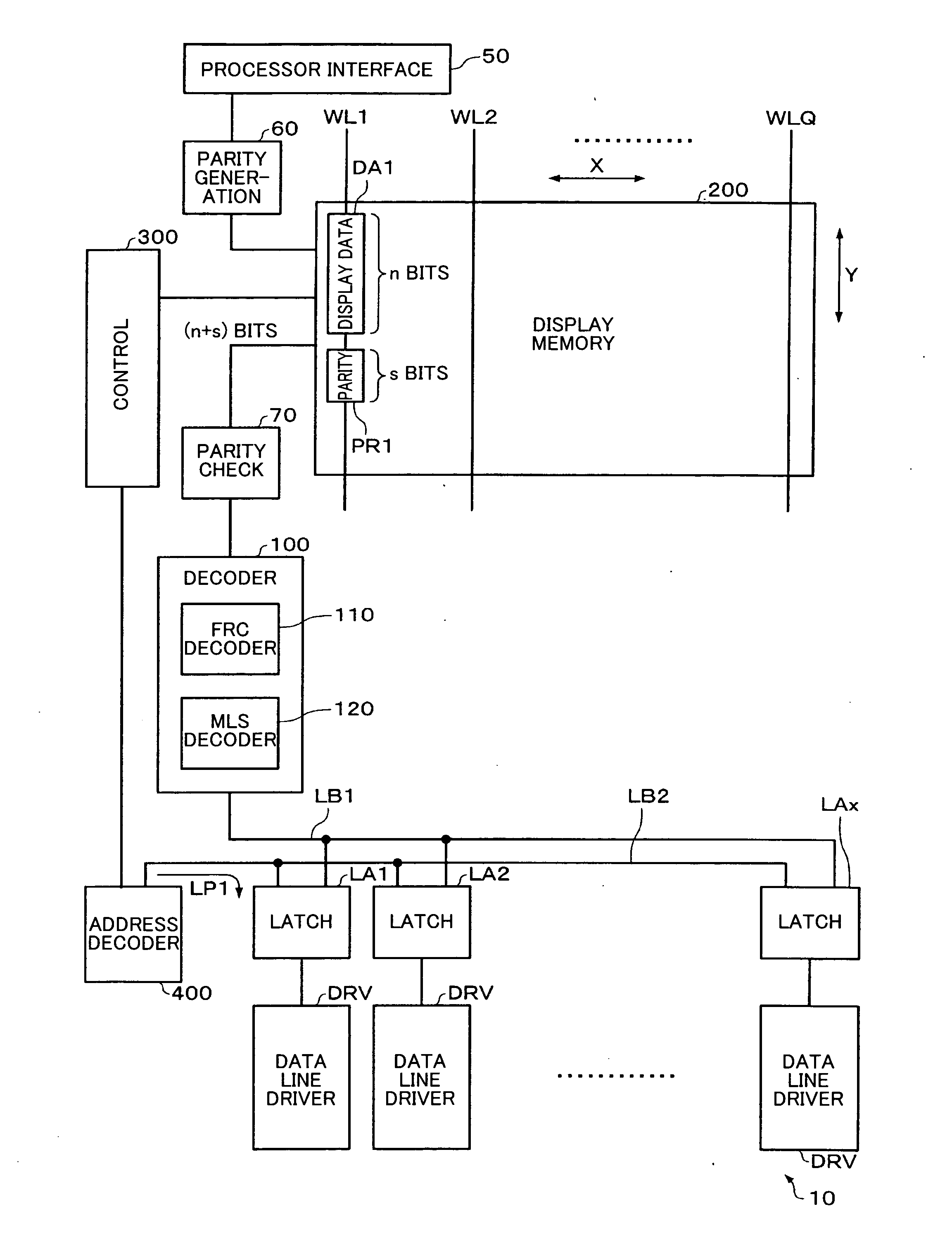
[0050] One embodiment of the present invention provides a display driver including: [0051] a parity generation circuit which generates s-bit (s is an integer of one or more) parity data for n-bit (n is an integer greater than one) display data input through a processor interface, combines the n-bit display data and the s-bit parity data, and outputs the combined n-bit display data and s-bit parity data to a display memory as (n+s)-bit display data; [0052] a parity check circuit which performs data error detection for the (n+s)-bit display data sequentially input from the display memory in units of (n+s) bits, and outputs the n-bit display data; [0053] at least one decoder which decodes the n-bit display...


PUM


Abstract

A display driver includes: a parity generation circuit which generates s-bit parity data for n-bit display data input through a processor interface, combines the n-bit display data and the s-bit parity data, and outputs the combined n-bit display data and s-bit parity data to a display memory as (n+s)-bit display data; a parity check circuit which performs data error detection for the (n+s)-bit display data sequentially input from the display memory in units of (n+s) bits, and outputs the n-bit display data; at least one decoder which decodes the n-bit display data output from the parity check circuit; a plurality of latch circuits which latch the data decoded by the decoder; and a plurality of data line driver sections which drive data lines of a display panel based on the data latched by the latch circuits.

Description

[0001] Japanese Patent Application No. 2004-85386, filed on Mar. 23, 2004, is hereby incorporated by reference in its entirety. BACKGROUND OF THE INVENTION [0002] The present invention relates to a display driver and an electronic instrument. [0003] In recent years, a display panel has been increasingly demanded accompanying an increase in functionality of electronic instruments. As a drive method for a display panel, various methods have been proposed. A driver circuit disclosed in Japanese Patent Application Laid-open No. 7-281636 has been known as an example. Japanese Patent Application Laid-open No. 7-281636discloses a circuit which drives a display panel by using 10 column drivers when the display panel includes 640×480 pixels, for example. A calculation circuit is provided in each column driver. Since the calculation circuit simultaneously processes display data for 7 lines×480 columns read from a memory, the calculation circuit becomes complicated and the circuit area is incr...

Claims


Application Information

Patent Timeline
IPC IPC(8): G06F3/14G02F1/133G09G3/20G09G3/36G09G5/00G09G5/10G09G5/393
CPCG06F3/1415G06F11/1032G09G2310/027G09G5/393G09G2310/0205G09G5/006A61H39/06A61K36/282A61H2201/0278A61H2201/025A61H2201/10A61N2005/066A61H2201/165
Inventor FUKUDA, MASAFUMIYASUE, TADASHI
Owner SEIKO EPSON CORP
Why Eureka
Try Eureka