Printer

Inactive Publication Date: 2005-09-29
NORITZ CORP
View PDF4 Cites 16 Cited by
  • Summary
  • Abstract
  • Description
  • Claims
  • Application Information

AI Technical Summary

Benefits of technology

[0013] An object of the present invention is to provide a printer capable of recording a plurality of frames of color images with a high processing performance with intending to reduce wasteful consumption of a recording medium and prevent the images from being deteriorated due to variation of load in conveyance of the recording medium, and capable of avoiding troublesomeness in dealing with the recording medium after image recording.

Problems solved by technology

In this printer, however, if the three thermal heads are pressurized onto the recording paper in the order of the thermal heads the printing position of which the recording paper has reached, the image to be recorded may be deteriorated due to variation of load in the conveyance of the recording paper.
As a result, any image can not be recorded in a region near the leading edge of the recording paper between the most upstream thermal head and the most downstream thermal head in the conveyance direction.
Such an operation of switching over the driving direction of the pair of conveyance rollers brings about a time loss.
Therefore, if the number of times of switching over the driving direction of the pair of conveyance rollers increases, the total time loss increases accordingly.
As a result, the processing performance of the printer lowers.
Thus, the techniques disclosed in JP-A-9-99572 and JP-A-2001-246769 can not realize a high processing performance.
This makes it troublesome to deal with the recording paper after image recording.

Method used


Image

  • Printer
  • Printer
  • Printer

Examples


Embodiment Construction

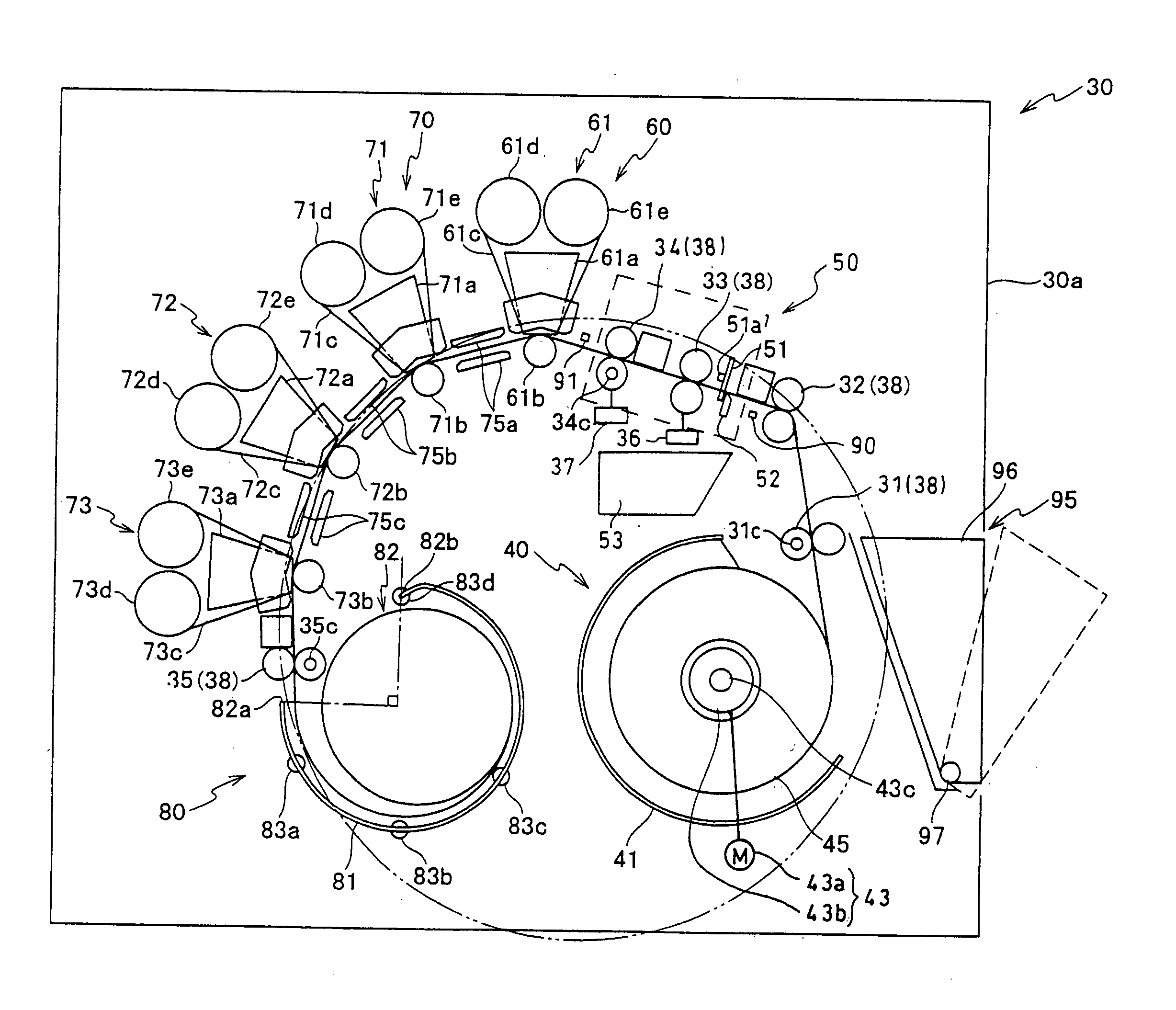
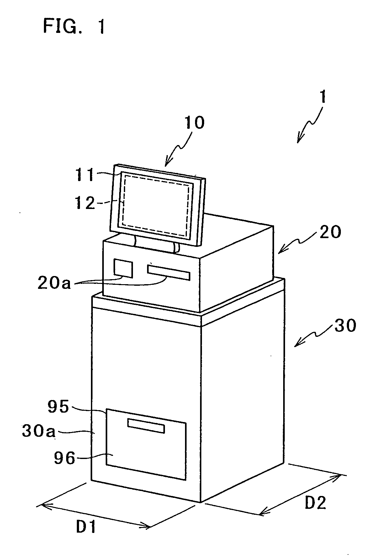
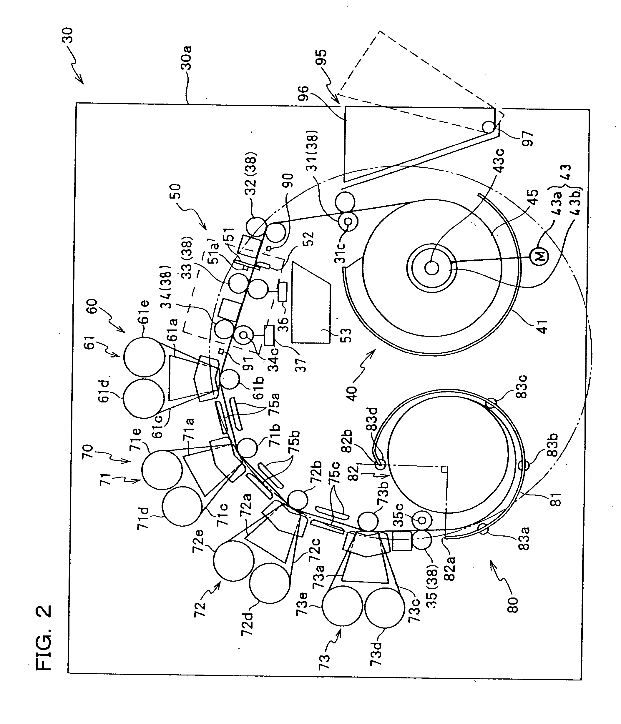
[0045] Hereinafter, a preferred embodiment of the present invention will be described with reference to drawings. FIG. 1 is an external perspective view of a printer according to an embodiment of the present invention. FIG. 2 is a view showing a general construction of a print unit of the printer of FIG. 1. FIG. 3 is an enlarged view of a region in the print unit enclosed with broken lines in FIG. 2. FIGS. 4A and 4B are views showing operations of a pair of conveyance rollers and a pair of sending-in rollers of the printer of FIG. 1. FIG. 5 is a block diagram showing principal components of the printer of FIG. 1 and a controller to which the components are connected.

[0046] A dye sublimation printer 1 as shown in FIG. 1 (hereinafter simply referred to as printer 1) includes an operation unit 10, a controller 20, and a print unit 30. The operation unit 10 serves for an operator to operate the printer 1. The operation unit 10 includes a display 11 for displaying thereon various kinds ...


PUM


Abstract

A printer includes a conveyance mechanism capable of conveying a long recording medium in a first direction from a supply unit storing therein the recording medium, toward an image recording unit capable of recording a color image on the recording medium, and in a second direction reverse to the first direction, with opposing the recording medium to the image recording unit; and a cutting unit capable of cutting the recording medium between the image recording unit and the supply unit. The conveyance mechanism is controlled to convey the recording medium in the first direction until a leading edge of the recording medium reaches a position distant in the first direction from the image recording unit, and then convey the recording medium in the second direction; and to form a slack portion of the recording medium being conveyed in the second direction, between the image recording unit and the cutting unit. The image recording unit is controlled to record frames of color images on the recording medium being conveyed in the second direction by the conveyance mechanism. The cutting unit is controlled to cut the recording medium being conveyed in the second direction.

Description

BACKGROUND OF THE INVENTION [0001] 1. Field of the Invention [0002] The present invention relates to a printer for recording color images on a recording medium. [0003] 2. Description of Related Art [0004] Various techniques are known in relation to printers each of which can record a color image on a recording medium. For example, JP-A-8-174876 discloses a one-path type color thermal printer having three thermal heads that can record colors of yellow, magenta, and cyan, respectively. The three thermal heads cooperate with each other to record a color image on a recording paper unwound from a recording paper roll and being conveyed in a paper feed direction. [0005] JP-A-9-99572 discloses a three-path type color thermal printer. In this printer, a portion of a heat-sensitive color recording paper of a length corresponding to one frame, unwound from a recording paper roll, is conveyed forward so as to be opposite to one thermal head, and then conveyed backward. In the backward conveyan...

Claims


Application Information

Patent Timeline
IPC IPC(8): B41J11/42B41J11/66
CPCB41J11/663B41J11/42
Inventor KITAMURA, NORIKAZUHABATA, MOTOHARUHASEGAWA, TAKAYUKI
Owner NORITZ CORP
Why Eureka
Try Eureka