Laser-based thermal printer

Active Publication Date: 2005-09-29
SILICON LIGHT MACHINES CORP
View PDF6 Cites 2 Cited by
  • Summary
  • Abstract
  • Description
  • Claims
  • Application Information

AI Technical Summary

Benefits of technology

[0008] In another embodiment, the thermal printer further includes a temperature sensor and a controller to control the heater to maintain a heated portion of the outer surface of the roller at a substantially constant temperature.
[0009] In another aspect, the present invention is directed to a thermal printer including a spatial light modulator assembly to modulate a light beam from a laser source according to electric fields applied to control reflective components within the assembly. The thermal printer further includes illumination optics for focusing the light beam onto the spatial light modulator assembly, and imaging optics disposed in

Problems solved by technology

However, close contact the thermal head and the heat-sensitive paper, can result in material being scraped from the paper by the thermal head.
This material can attach to the thermal head separating it from the heat-sensitive paper, resulting in incomplete or incorrect recording of images.
In addition, close contact between thermal head and the paper can result in the thermal head being damaged or destroyed.
However, conventional implementations of this approach have not been satisfactory for a number of reasons.

Method used


Image

  • Laser-based thermal printer
  • Laser-based thermal printer
  • Laser-based thermal printer

Examples


Embodiment Construction

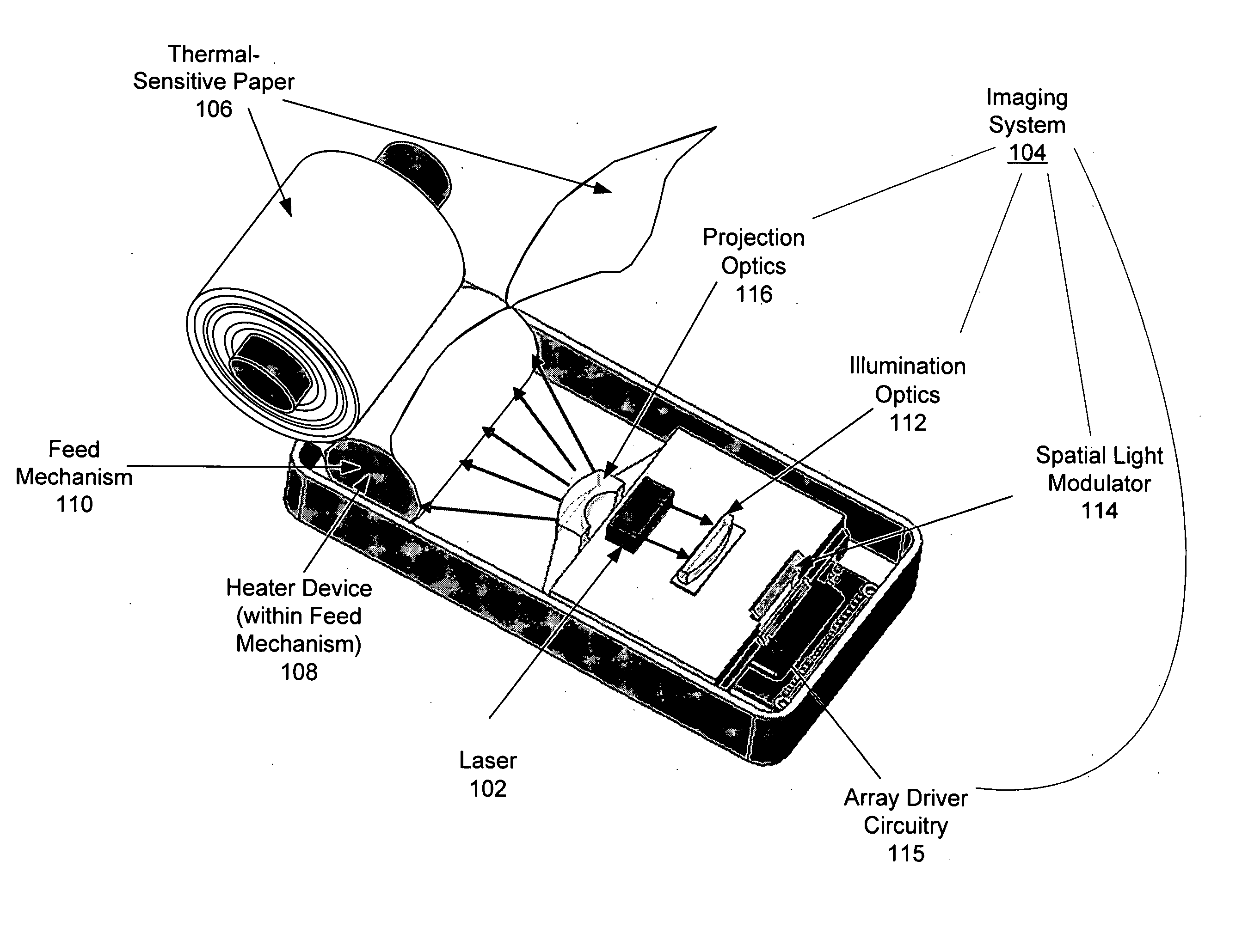
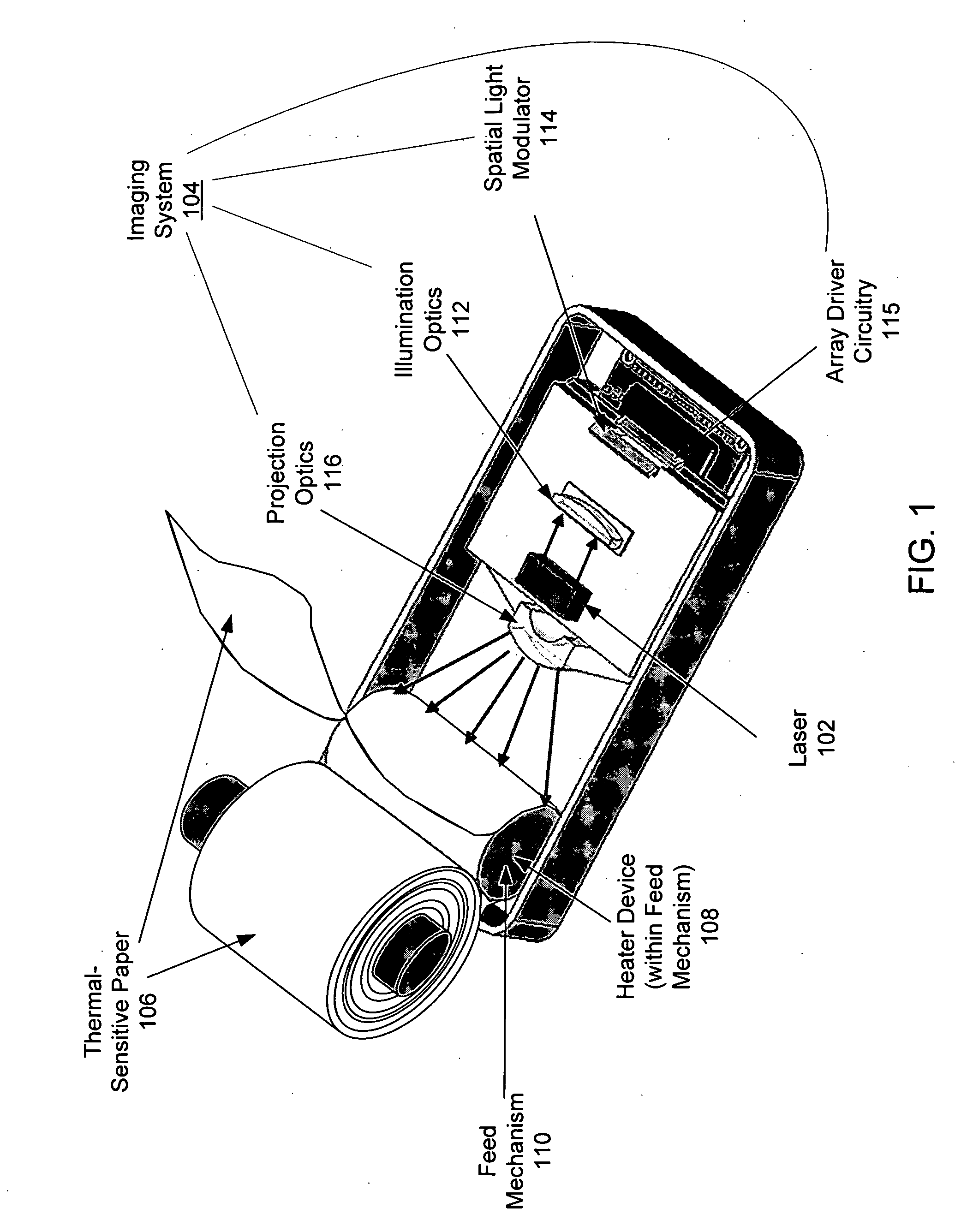
[0017] As discussed above, thermal printers have various problems and disadvantages. Using lasers as a heat source for thermal printing has been proposed, but conventional implementations of laser-based have various problems. These problems are now discussed.

[0018] One problem, is the relatively high threshold above which the heat-sensitive paper must be heated by the laser light in order to produce a change in color of the paper. This high threshold is required to provide a highly stable heat-sensitive paper having an adequate shelf life, and capable of being used in a wide range of environmental conditions. As a result the laser should preferably output a considerable amount of thermal energy to record an image on the paper. This high energy output requirement increases the size, complexity and cost of the laser thermal printer, and, in addition, can shorten laser life leading to higher operating costs.

[0019] Other problems with conventional laser-based thermal printers arise fr...


PUM


Abstract

One embodiment described pertains to a thermal printer is provided having a spatial light modulator (SLM) to modulate light from a laser source to record information on a thermal-sensitive surface of a recording medium, and a heater adjacent to the medium to preheat the thermal-sensitive surface prior to recording of information thereon. The printer may further include illumination optics for focusing the light beam onto the SLM, and imaging optics to image the light on the thermal-sensitive surface. The heater may comprise a resistive, a convective or a radiant heater. The printer may further include a feed mechanism with a roller having an outer surface in contact with the recording medium for feeding it past the imaging optics, and the heater may be disposed inside of the roller to heat the recording medium in contact with the roller. The heater may be arranged to heat the entire outer surface of the roller, or only a portion thereof. Other embodiments are also described.

Description

REFERENCE TO RELATED APPLICATIONS [0001] The present application claims the benefit of U.S. provisional application No. 60 / 556,657, entitled “Laser Photothermal Printer Using Heating to Improve Paper Sensitivity,” filed Mar. 26, 2004, by inventors Harold Zarem and Omar S. Leung, the disclosure of which is hereby incorporated by reference.TECHNICAL FIELD [0002] The present invention relates generally to thermal printers. BACKGROUND OF THE INVENTION [0003] Thermal printers in which a thermal head scans in close contact with the surface of a heat-sensitive recording material or paper to record an image or other information thereon are widely known and used. The thermal head typically uses a resistive element as a heat source. Such systems are commonly employed in a facsimile, and in printers for registers, and other applications. However, close contact the thermal head and the heat-sensitive paper, can result in material being scraped from the paper by the thermal head. This material c...

Claims


Application Information

Patent Timeline
IPC IPC(8): B41J2/315B41J2/32
CPCB41J2/32
Inventor ZAREM, HAROLD A.LEUNG, OMAR S.
Owner SILICON LIGHT MACHINES CORP
Why Eureka
Try Eureka