Blending tank with heating function for lubricating oil production

A lubricating oil and blending technology, which is applied to mixers with rotating stirring devices, transportation and packaging, chemical instruments and methods, etc., can solve the problems of affecting the performance of finished products, the decline of finished product performance, and large temperature difference changes, so as to ensure stable performance , Prevent violent fluctuations and reduce the effect of impact

Pending Publication Date: 2022-02-08
陈凌轶
View PDF0 Cites 0 Cited by
  • Summary
  • Abstract
  • Description
  • Claims
  • Application Information

AI Technical Summary

Problems solved by technology

[0002] Lubricating oil is often used in the transmission system of mechanical equipment to reduce the friction between the transmission structures. The performance of the lubricating oil determines the energy transfer efficiency of the transmission system to a certain extent; some compound lubricating oils During production, it is necessary to mix different raw materials at a specific temperature to ensure that the finished product with up to standard performance is prepared; most of the lubricating oil heating and stirring equipment in the prior art is produced by the abbreviated heating method, which makes the temperature of the raw materials during the production process There will be obvious vibrations, resulting in a decrease in the performance of the finished product. In addition, this type of equipment always adds low-temperature raw materials when adding single-quality raw materials, which will cause a large temperature difference during the production process and affect the performance of the finished product. It needs to be improved.

Method used


Image

  • Blending tank with heating function for lubricating oil production
  • Blending tank with heating function for lubricating oil production
  • Blending tank with heating function for lubricating oil production

Examples


Embodiment Construction

[0026] The present invention will be further described below with reference to the accompanying drawings.

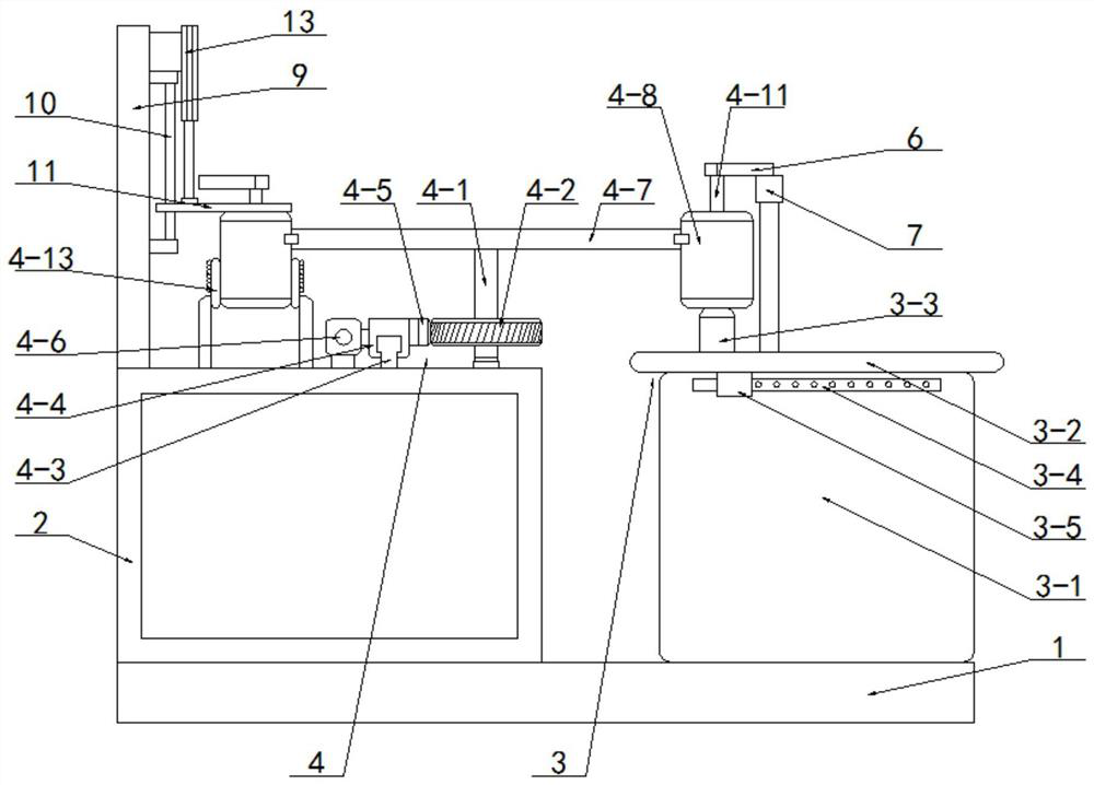
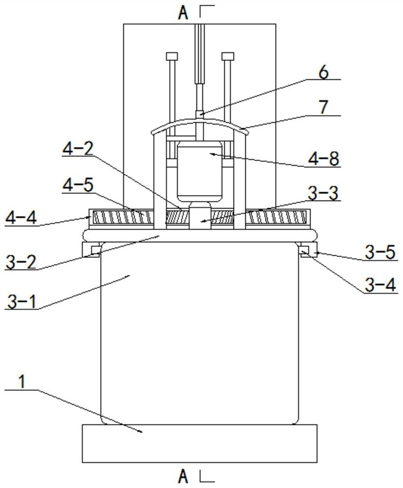
[0027] See Figure 1 - Figure 6 As shown, the specific embodiment includes a base 1, a stirring assembly 3, a preheating assembly 4, wherein the agitation assembly 3 is fixed to the base 1, and the base 1 is fixed to the base 1, and the bracket 2 is disposed at the left of the stirring assembly 3. On the side, the preheating assembly 4 is fixed to the bracket 2, and the outlet end of the preheating assembly 4 is disposed above the inlet end of the agitation assembly 3;

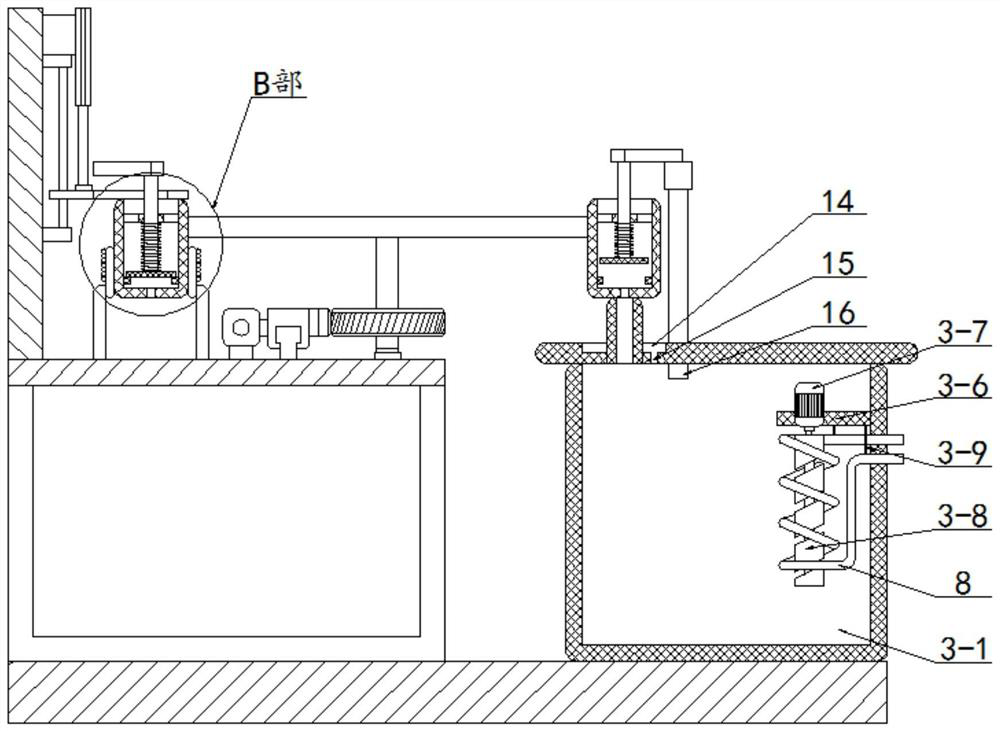
[0028]The stirring assembly 3 comprises a stirred tank 3-1, a No. 1 panel 3-2, a bracket 2, a waterproof motor 3-7, a spiral stirring roller 3-8, a hot wire 3-9, wherein the mixture 3 -1 riveting on the base 1, the upper end opening of the stirred kettle 3-1, the upper end of the stirrer 3-1 is covered with one panel 3-2, and the No. 1 panel 3-2 is wearing fixed tube 3-3 5 Slide is placed on a rail 3-4, and t...


PUM


Abstract

The invention discloses a blending tank with a heating function for lubricating oil production, and relates to the technical field of lubricating oil production equipment, the blending tank comprises a base, a stirring assembly and a preheating assembly, the stirring assembly is fixedly arranged on the base, a support is fixedly arranged on the base, the support is arranged on the left side of the stirring assembly, and the preheating assembly is fixedly arranged on the support; the outlet end of the preheating assembly is arranged above the inlet end of the stirring assembly; a continuous heating device is arranged in the stirring device, continuous heating can be conducted during stirring and blending, the constant temperature in the product production process is guaranteed, the preheating device is arranged, raw materials needing to be added can be independently heated, and it is guaranteed that the temperature of the raw materials is kept consistent with that of semi-finished products when the raw materials are added; and good performance of a finished product is ensured.

Description

Technical field [0001] The present invention relates to the technical field of lubricating oil production equipment, and in particular to a lubricating oil having a heating function. Background technique [0002] Lubricating oil is often used in the transmission system in the mechanical equipment to reduce the friction between the transmission structure, and the performance of the lubricant determines the energy transfer efficiency of the transmission system to a certain extent. Partial composite lubricant In production, different raw materials need to be mixed at a particular temperature to ensure the preparation of the finished product of the standard; the prior art lubricating oil heating mixing equipment is mostly used in the abnormal heating method, which makes the raw material in the production process during production There will be obvious dial, resulting in a decrease in finished product, and such equipment is added to the low temperature raw material when adding a singl...

Claims


Application Information

Patent Timeline
IPC IPC(8): B01F35/93B01F35/32B01F27/92B01F27/17B01F101/39
CPCY02P70/10
Inventor 陈凌轶
Owner 陈凌轶
Why Eureka
Try Eureka