Image forming apparatus and image formation control method

a technology of image forming apparatus and control method, which is applied in the direction of electrographic process, instruments, transportation and packaging, etc., can solve the problems of image position precision deterioration in proportion to print speed, image position precision also deterioration, etc., to eliminate any drop in image position precision, precisely adjust the image position all the time, the effect of high precision

Inactive Publication Date: 2005-09-29
CANON KK
View PDF5 Cites 2 Cited by
  • Summary
  • Abstract
  • Description
  • Claims
  • Application Information

AI Technical Summary

Benefits of technology

[0008] It is an object of the present invention to provide an image forming apparatus, which can detect the paper feed timing with high precision, can eliminate any drop of the image position precision due to mechanical attachment errors and durability of components, and can precisely adjust the image position all the time.
[0012] According to the above arrangement, since an image is recorded on a paper sheet in consideration of the detected correction value as mounting error data of the sheet read unit in addition to the leading end detection data or widthwise end detection data, the need for calculating correction parameters for each correction can be obviated, and image recording with very high positional precision can be assured.
[0013] Since the image recording position precision can be improved in both the main scan and sub-scan directions, image formation with precise image recording positions in both the main scan and sub-scan directions can be achieved.

Problems solved by technology

Especially, when a high-speed print process is done, the image position precision deteriorates in proportion to the print speed due to the coupling time of the registration clutch.
When a high-speed print process is done, the image position precision also deteriorates due to some detection error of the paper feed timing by the sensor, mechanical attachment errors and durability of components, and the like.

Method used


Image

  • Image forming apparatus and image formation control method
  • Image forming apparatus and image formation control method
  • Image forming apparatus and image formation control method

Examples


Embodiment Construction

[0031] An embodiment of an image forming apparatus and its control method according to the present invention will be described in detail hereinafter with reference to the accompanying drawings. Note that building components described in this embodiment are merely examples, and do not limit the scope of this invention. The same reference numerals denote the same parts throughout the drawings, and a repetitive description thereof will be avoided.

[Overall Arrangement]

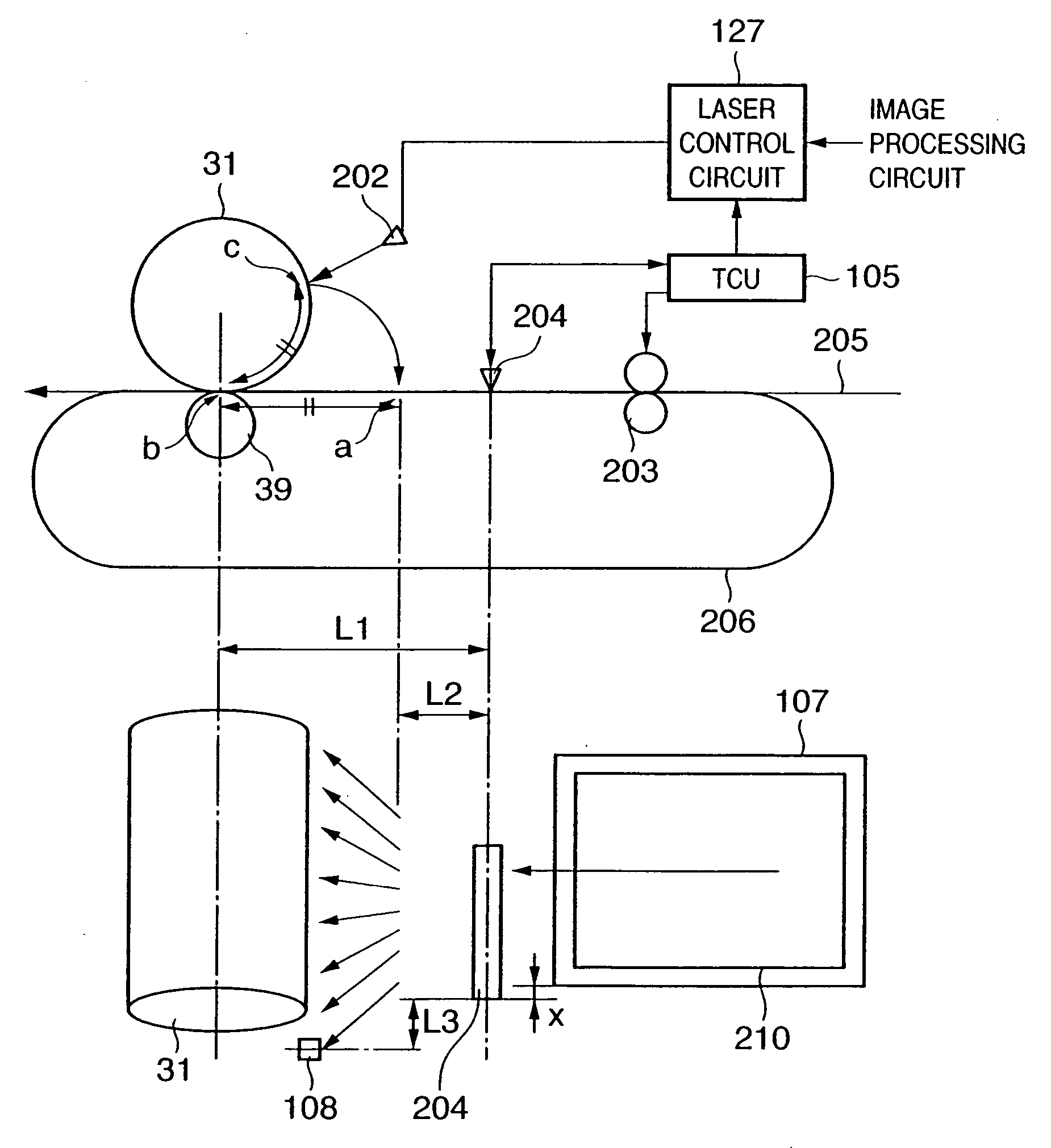
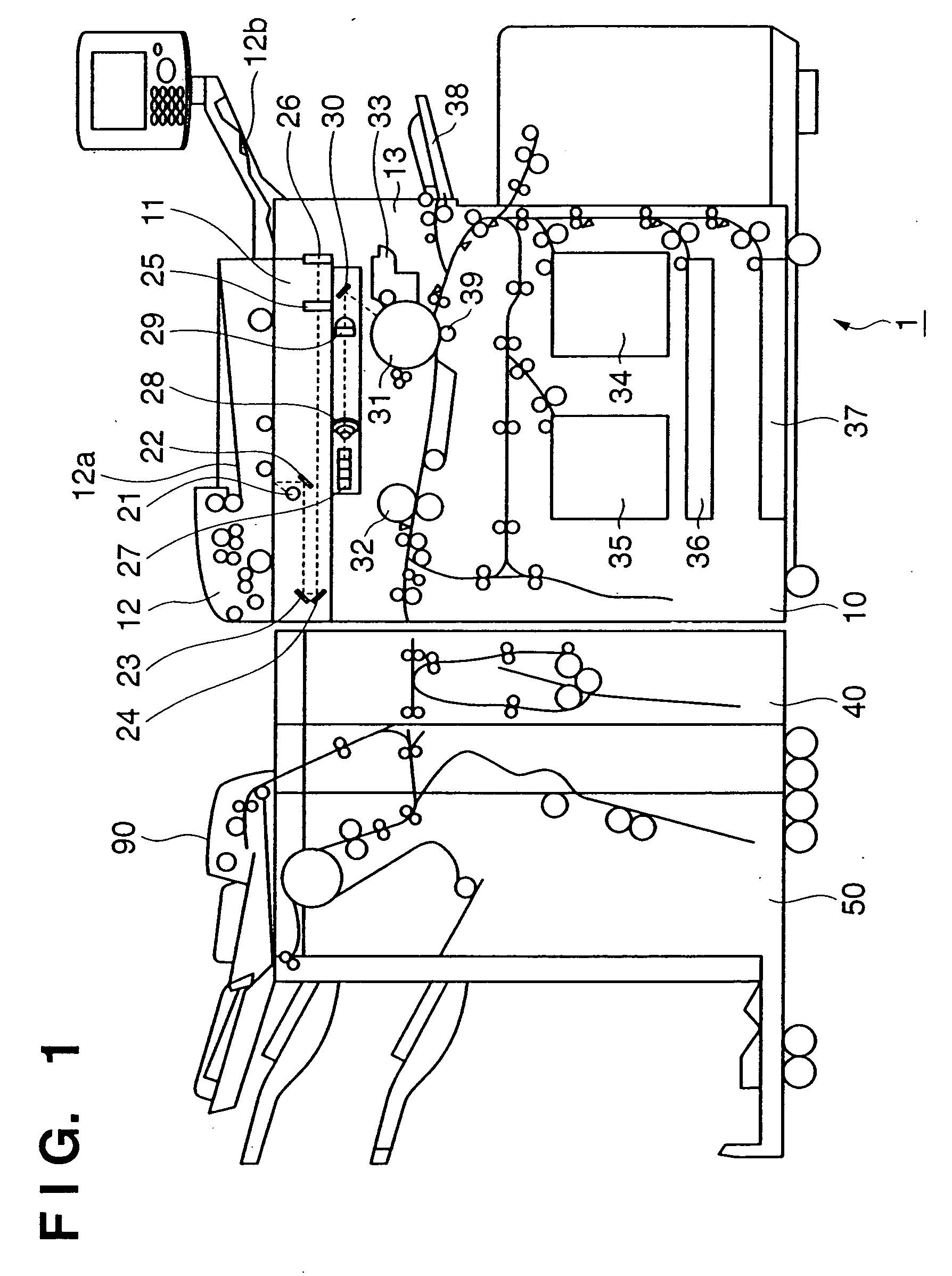
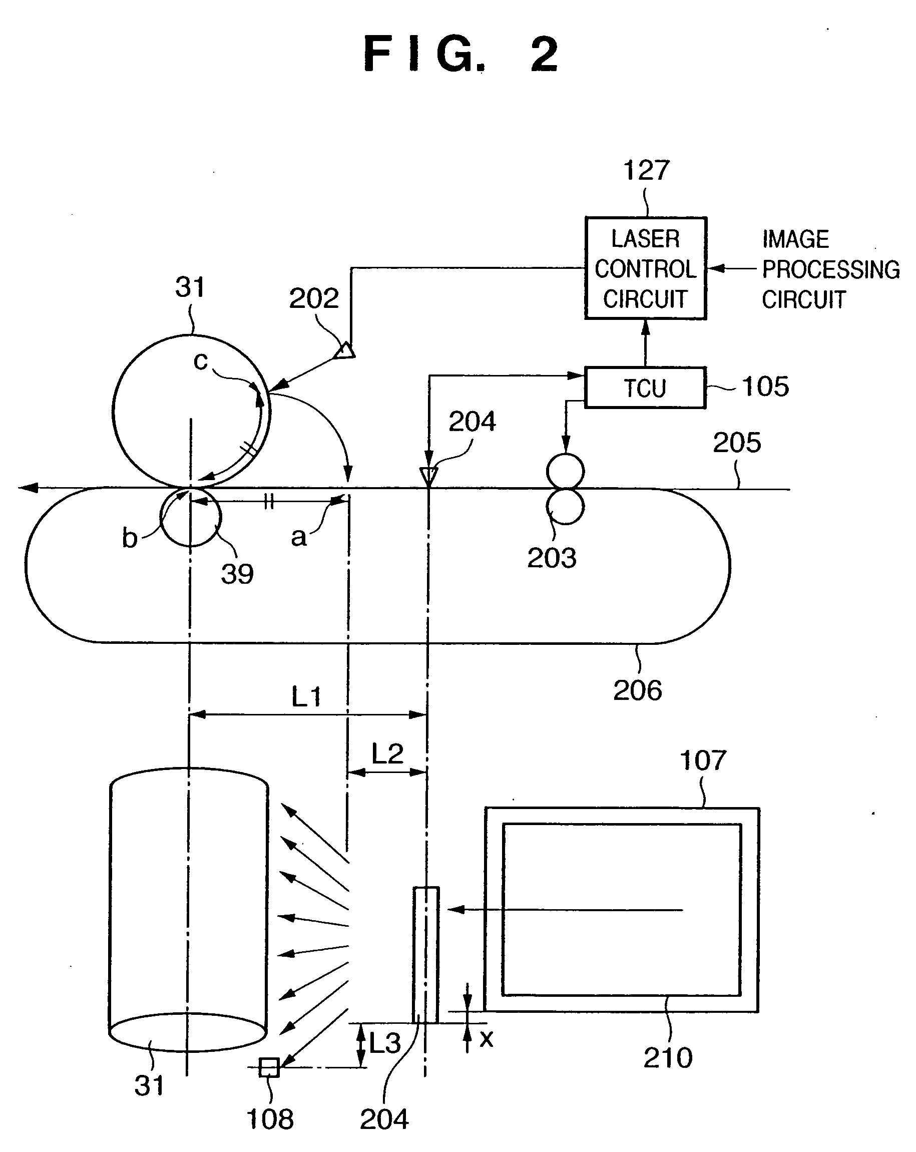
[0032]FIG. 1 is a view showing the structure of an image forming apparatus 1 according to an embodiment of the present invention. This image forming apparatus 1 is comprised of an image forming apparatus main body 10, folding device 40, and finisher 50. The image forming apparatus main body 10 is comprised of an image reader 11 for reading a document image, and a printer 13.

[0033] A document feeder 12 is mounted on the image reader 11. The document feeder 12 feeds documents, which are set facing up on a document tray 12...


PUM


Abstract

A frame image (210) with 5-mm wide margins is formed on a paper sheet on the basis of the leading end and widthwise end positions of the paper sheet (107) detected by a contact image sensor (CIS) (204) in an adjustment mode. After that, this paper sheet (107) is circulated to a feed position via a circulating path (206) and paper convey path (205), and the CIS (204) detects the frame image position formed on the circulated paper sheet and its paper end portion so as to detect errors from the 5-mm wide margins. Correction values which can cancel these errors are stored in a correction parameter storage unit (71), and forming start timing control is made using these correction values upon forming an image in an actual job. In this way, an image forming apparatus which can detect the paper feed timing with high precision, can eliminate deterioration of the image position precision due to mounting errors and durability of components, and can always precisely adjust the image position is provided.

Description

TECHNICAL FIELD [0001] The present invention relates to an image forming apparatus such as an LBP (laser beam printer), copying machine, or the like that uses, e.g., an electrophotographic technique. BACKGROUND ART [0002] A conventional image forming apparatus will be described below. FIG. 16 shows the structure of a print position adjustment mechanism in a conventional image forming apparatus. FIG. 16 shows a photosensitive drum 31, a laser device 202 which forms a latent image on the photosensitive drum 31, a registration clutch (to be also referred to as registration rollers hereinafter) 203 which determines the paper feed timing, a paper sensor 1204 for detecting a paper sheet to be conveyed, a deviation amount detection sensor 1205 which detects the deviation amount of the widthwise end in a direction (to be also referred to as a widthwise direction hereinafter) perpendicular to the paper feed direction, an output paper sheet 107, and a paper convey path 205. [0003] In the prin...

Claims


Application Information

Patent Timeline
Patent Type & Authority Applications(United States)
IPC IPC(8): B65H7/08B41J29/38B65H7/10B65H9/14G03G15/00G03G21/00G03G21/14H04N1/04
CPCG03G2215/00578G03G15/6579
Inventor MORITA, TETSUYA
Owner CANON KK
Why Eureka
Try Eureka