Connector to be mounted to a board and ground structure of the connector

Inactive Publication Date: 2005-09-29
JAPAN AVIATION ELECTRONICS IND LTD
View PDF12 Cites 105 Cited by
  • Summary
  • Abstract
  • Description
  • Claims
  • Application Information

AI Technical Summary

Benefits of technology

[0005] It is therefore an object of the present invention to provide a connector to be mounted to a boar

Problems solved by technology

However, in such a structure in which the terminal portions of the ground plates are contacted with each other within each single through hole, the board is inevitably increased in thickness.
This is

Method used


Image

  • Connector to be mounted to a board and ground structure of the connector
  • Connector to be mounted to a board and ground structure of the connector
  • Connector to be mounted to a board and ground structure of the connector

Examples


Embodiment Construction

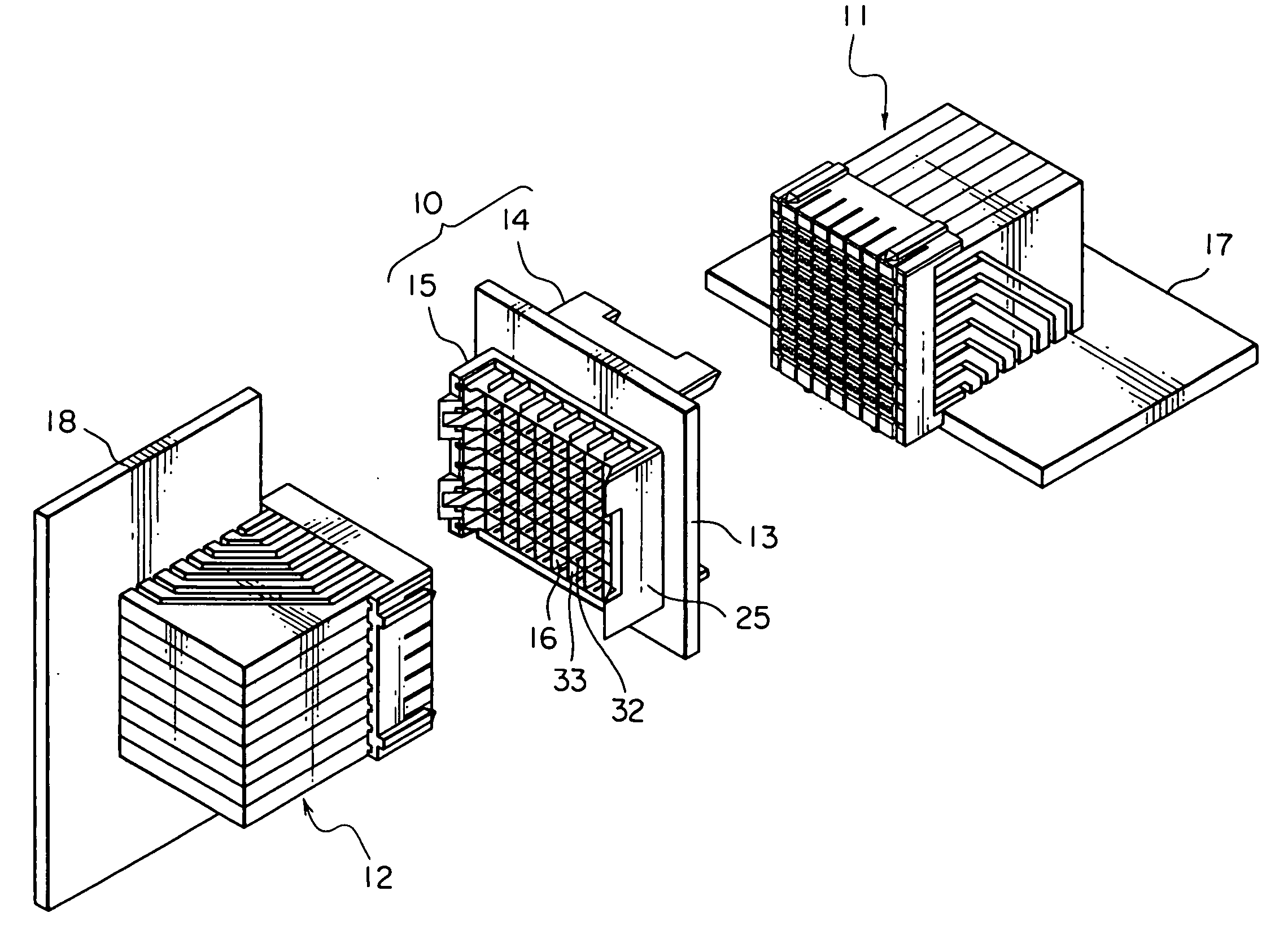
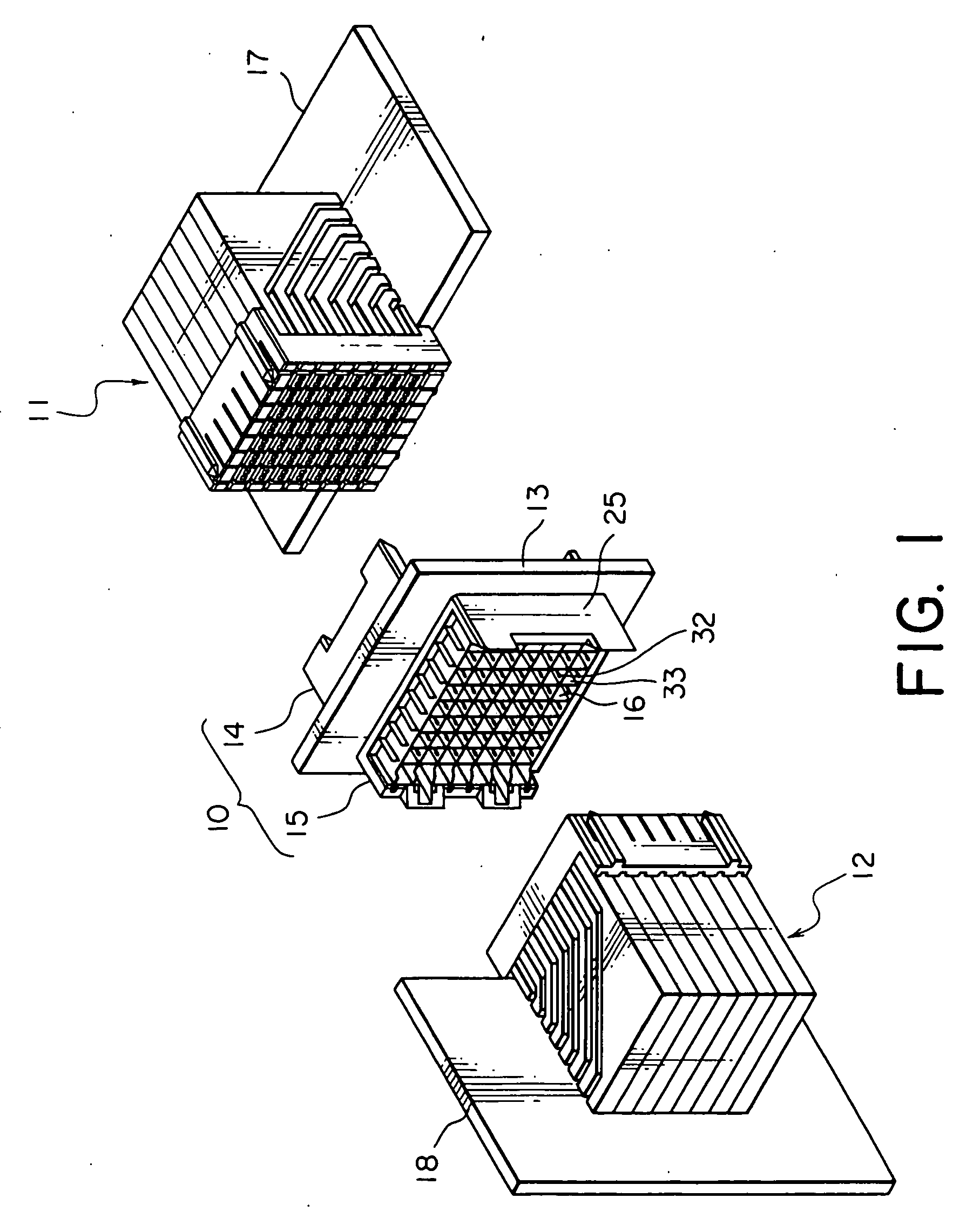
[0023] Referring to FIG. 1, description will be made of a receptacle connector 10 as a connector according to one embodiment of the present invention and first and second plug connectors 11 and 12 to be connected to the receptacle connector 11 and 12.

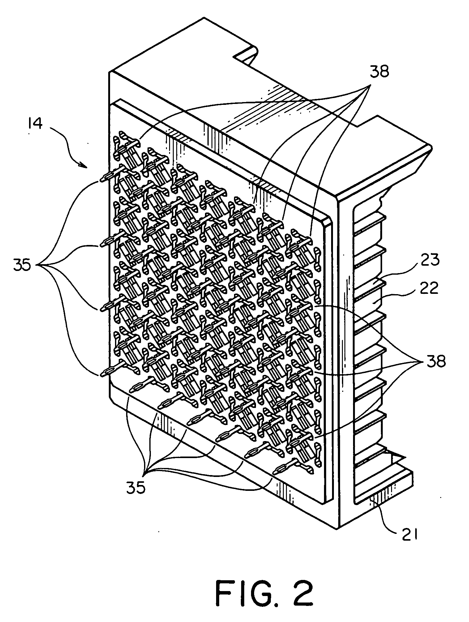
[0024] The receptacle connector 10 comprises a board 13 called a mid-plane, a first half portion 14 disposed on one surface or a first surface of the board 13, a second half portion 15 disposed on the other surface or a second surface of the board 13 opposite to the first surface, and several tens signal contacts 16 used in common in the first and the second half portions 14 and 15.

[0025] The first plug connector 11 is mounted to a board 17 placed in a horizontal direction and is adapted to be engaged with and disengaged from the first half portion 14 of the receptacle connector 10. The second plug connector 12 is mounted to a board 18 placed in a vertical direction and is adapted to be engaged with and disengaged from the second half...


PUM


Abstract

In a connector mounted on a board having a number of through holes, first and second housing are disposed on opposite surfaces of the board. A conductive contact is inserted through the through holes, respectively, and held by the first and the second housings. The contact has first and second contacting portions which are formed at opposite ends thereof and protrude from the first and the second housings, respectively. A first ground is held by the first housing and surrounds the first contacting portion. A second ground is held by the second housing and surrounds the second contacting portion. The first ground has a plurality of terminal portions protruding from the first housing towards the board and arranged in a first staggered pattern. The second ground has a plurality of terminal portions protruding from the second housing towards the board and arranged in a second staggered pattern. The terminal portions are inserted into the through holes, respectively.

Description

BACKGROUND OF THE INVENTION [0001] This invention relates to a connector to be mounted to a board and a ground structure of the connector. [0002] A connector of the type is disclosed, for example, in Japanese Patent Application Publication (JP-A) No. 2002-33162. The connector is adapted to be mounted to a board, such as a circuit board having a number of through holes. The connector comprises a pair of insulating housings disposed on opposite surfaces of the board and a plurality of conductive contacts inserted through the through holes and held by the housings. Each of the contacts has opposite ends protruding from the housings and serving as contacting portions. Each of the housings holds a conductive ground adjacent to the contacting portions of the contacts. The ground is expected to exhibit an electromagnetic shielding effect. [0003] Each of the grounds has a plurality of terminal portions protruding from the housing towards the board and inserted into the through holes. The te...

Claims


Application Information

Patent Timeline
IPC IPC(8): H01R12/16H01R13/514H01R13/648H01R13/658H01R31/06
CPCH01R9/096H01R12/585H01R31/06H01R23/688H01R13/514H01R12/52H01R13/6471H01R13/6594
Inventor TOKUNAGA, TAKASHI
Owner JAPAN AVIATION ELECTRONICS IND LTD
Why Eureka
Try Eureka