SiO2-TiO2 glass body with improved resistance to radiation

Active Publication Date: 2005-09-29
ASAHI GLASS CO LTD
View PDF9 Cites 25 Cited by
  • Summary
  • Abstract
  • Description
  • Claims
  • Application Information

AI Technical Summary

Benefits of technology

[0010] It is a third object of the invention to disclose a manufacturing process for the production of an impro

Problems solved by technology

As a result, instead of being moderated by the layers near the mask surface, an ever greater part of the electron beam will penetrate into and damage the substrate material below those layers.
That damage normally makes itself felt by compaction of the material in the irradiat

Method used


Image

  • SiO2-TiO2 glass body with improved resistance to radiation
  • SiO2-TiO2 glass body with improved resistance to radiation

Examples


example

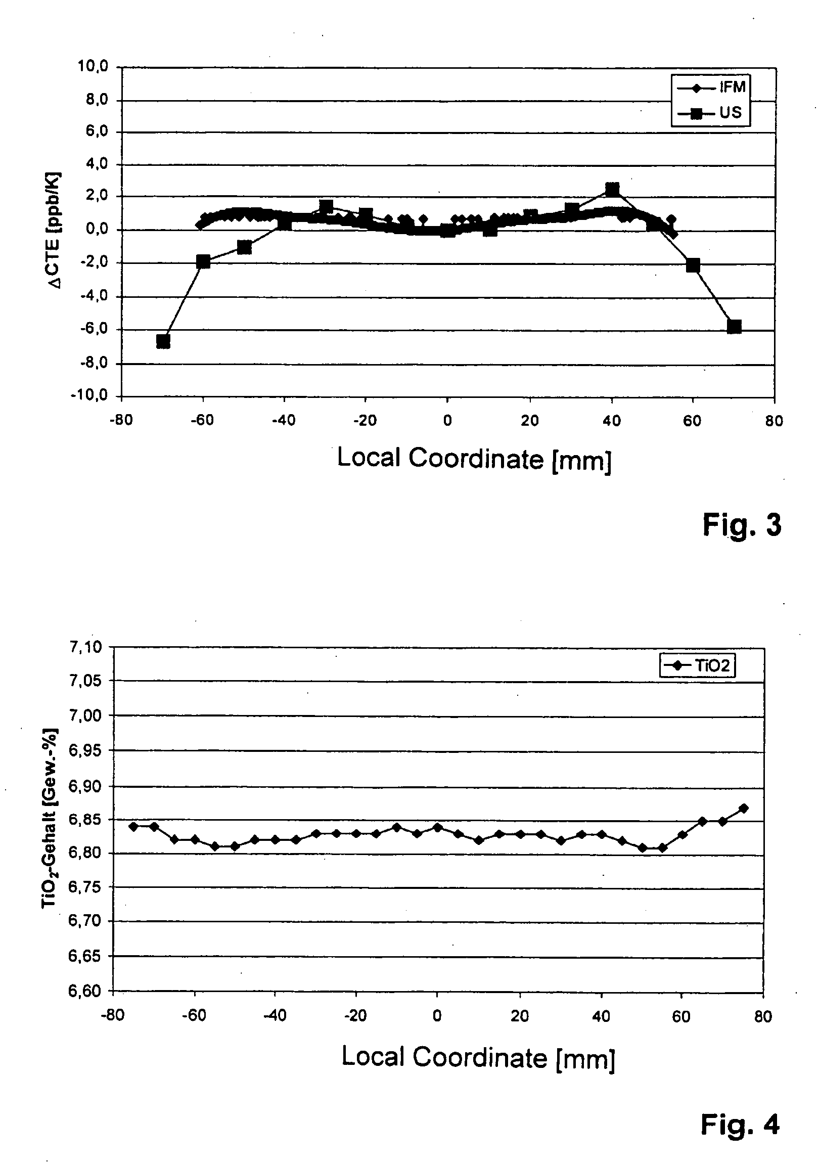
[0033] An SiO2—TiO2 quartz glass cylinder is produced from SiCl4 and TiCl4 by the flame-hydrolysis process as described in U.S. Pat. No. 6,595,030. The quartz glass body so obtained showed the homogeneity of Ti content and CTE illustrated in FIG. 3 and FIG. 4. Starting out from the cylinder, mask substrates having a diameter of 6 inches were produced by cutting, remolding, lapping and polishing.

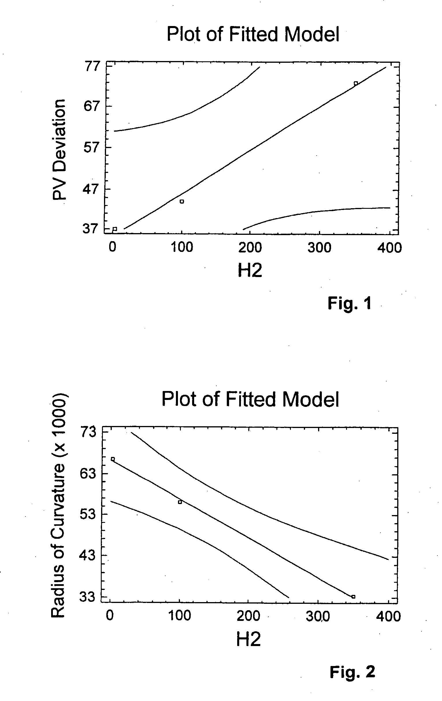
[0034] Three polished mask substrates of 6 inches in diameter, with different H2 concentrations, were first subjected to an initial flatness measurement, whereafter the entire lower surfaces of the substrates were irradiated with electrons in identical way. This was followed by a second flatness measurement and determination of the distortion of the substrate. To this end, both the induced radius of curvature and the variation of the PV value can be used as measure of flatness variation.

[0035] The distortion of the substrate and the H2 content in the glass show a strong linear correlation, ...


PUM

PropertyMeasurementUnit
Timeaaaaaaaaaa
Timeaaaaaaaaaa
Diameteraaaaaaaaaa

Abstract

The invention discloses an SiO2—TiO2 glass, which is preferably made by flame-hydrolysis and which distinguishes itself by increased resistance to radiation, especially in connection with EUV lithography. By purposefully reducing the hydrogen content, clearly improved resistance to radiation and reduced shrinking is achieved.

Description

BACKGROUND OF THE INVENTION [0001] The present invention relates to an SiO2—TiO2 glass suited especially for components used in EUV lithography, such as substrate materials for reflective mirror optics and masks or the like. [0002] During a lithographic process, the structures for integrated circuits present on the mask are transferred to a silicon wafer by projection of laser radiation of a given wavelength. Especially in EUV lithography a wavelength of approximately 13 nm is used. Given the fact that there do not exist any materials that are pervious to light of that wave-length, reflective masks and optics are used in that process. It is the object of that technique to realize on the silicon wafer structures in widths of up to 35 nm. [0003] SiO2—TiO2 glasses with a TiO2 content in the range of between approximately 6 and 8 percent by weight, for example, are employed as a preferred material in the production of components for EUV lithography, the thermal expansion occurring in th...

Claims


Application Information

Patent Timeline
IPC IPC(8): C03B19/01C03B32/00C03C3/04C03C3/06C03C4/00
CPCC03C3/06C03C2201/21C03C2203/50C03C2203/44C03C2201/42
Inventor ALKEMPER, JOCHENSCHUHMACHER, JOERGHACK, HRABANUSSOHR, OLIVER
Owner ASAHI GLASS CO LTD
Why Eureka
Try Eureka