Spinal fixation element and methods

a technology for spinal fixation and elements, applied in the field of spinal fixation elements, tools and methods, can solve the problems of undefeated lengthening of surgical procedures, significant damage to surrounding tissue and muscle, and difficulty in elongating spinal fixation elements using minimally invasive techniques

Active Publication Date: 2005-09-29
DEPUY SPINE INC (US)
View PDF59 Cites 256 Cited by
  • Summary
  • Abstract
  • Description
  • Claims
  • Application Information

AI Technical Summary

Benefits of technology

[0006] In one embodiment, the spinal fixation element can be provided as part of a spinal implant kit containing an access device having an inner lumen extending between proximal and distal ends, and at least one opening formed in a sidewall thereof adjacent to the distal end. The sidewall opening(s) in the access device can vary in shape and size, but it preferably extends from the distal end of the access device and terminates distal to the proximal end of the access device, and more preferably the opening(s) has a length that is greater than a length of the spinal fixation element. In an exemplary embodiment, the access device includes opposed openings formed therein. In use, the feature on the spinal fixation element can be sized to prevent passage thereof through the opening, and more preferably the feature has a width that is greater than a width of the opening in the sidewall of the access device to prevent passage of the feature therethrough, thus facilitating positioning of the spinal fixation element with respect to a spinal anchor coupled to the access device.

Problems solved by technology

However, generally elongate spinal fixation elements can be difficult to implant using minimally invasive techniques.
While this procedure offers advantages over prior art invasive techniques, the transverse introduction of the rod can cause significant damage to surrounding tissue and muscle.
Moreover, the use of three separate access sites can undesirably lengthen the surgical procedure.

Method used


Image

  • Spinal fixation element and methods
  • Spinal fixation element and methods
  • Spinal fixation element and methods

Examples


Embodiment Construction

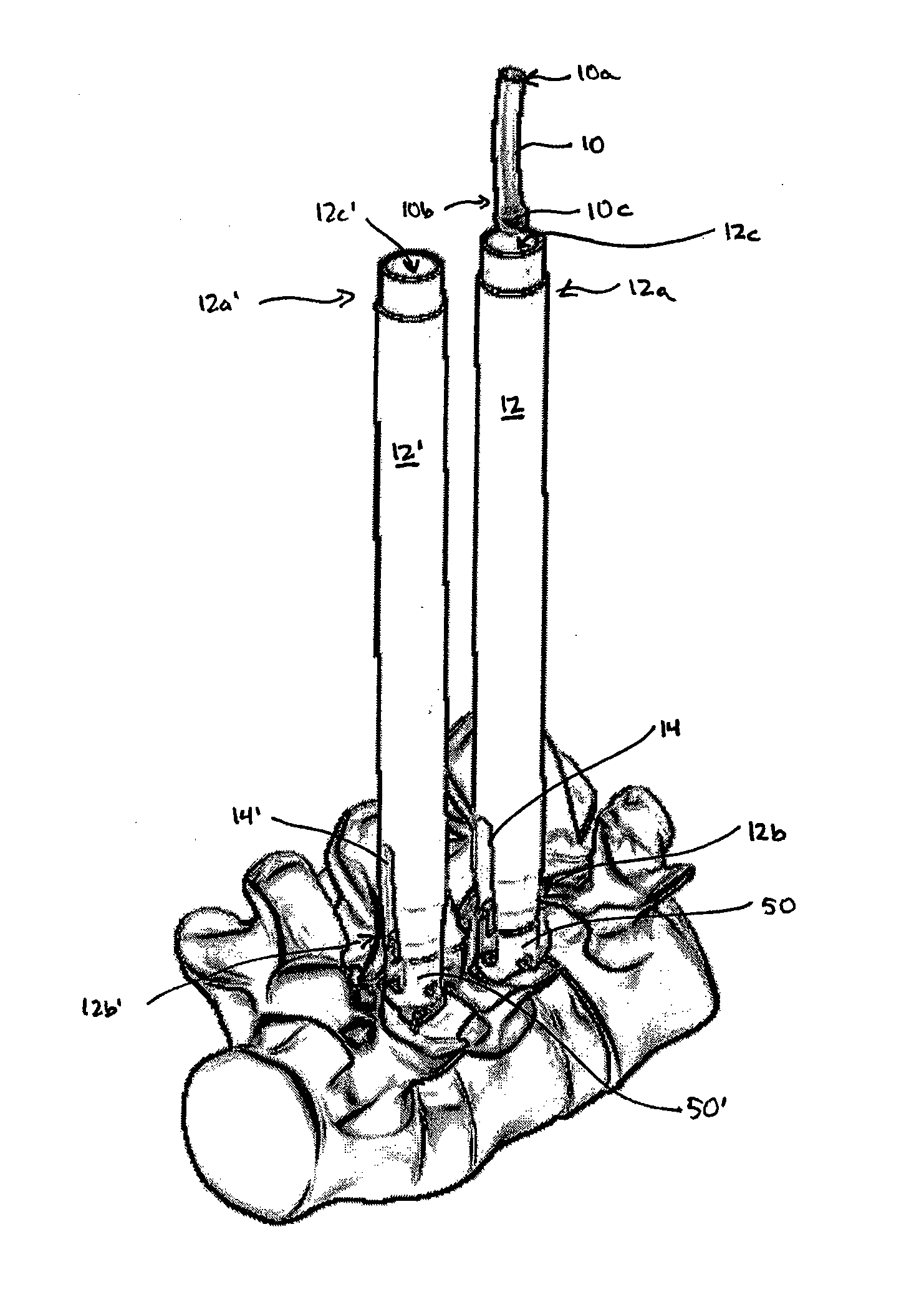
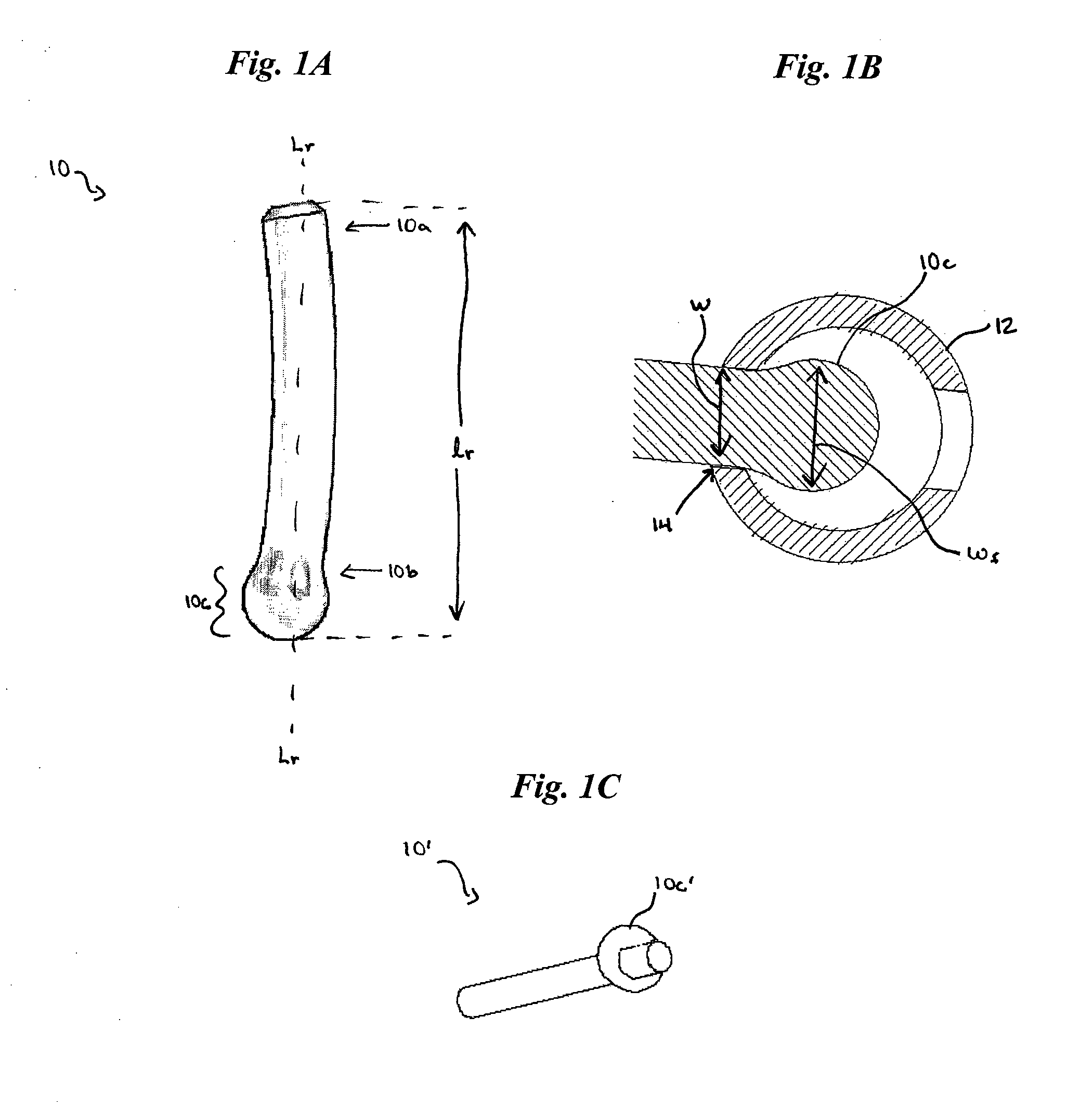
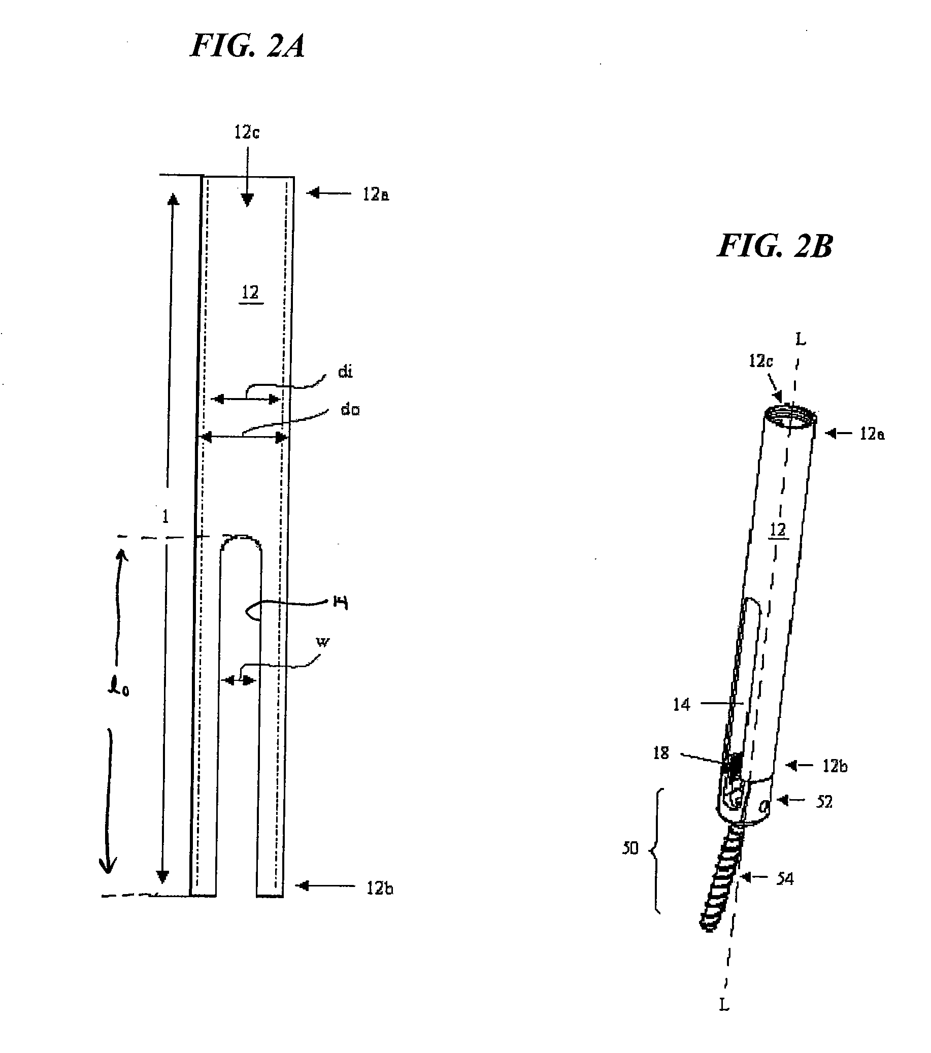
[0026] The present invention provides a spinal fixation element, such as a spinal rod, having a feature formed thereon that facilitates placement of the spinal fixation element through an access device, thus allowing the spinal fixation element to be positioned in relation to a spinal anchor that is coupled to the access device and that is implanted in a vertebra in a patient's spine. The feature also optionally facilitates placement of the spinal fixation element in relation to one or more spinal anchors implanted in adjacent vertebrae. In particular, the spinal fixation element is adapted for use with an access device that has at least one slot or opening formed therein and having a width that is less than a width of the feature, thus preventing the feature from passing therethrough. The spinal fixation element can therefore be inserted through the access device, and a portion of the fixation element can be passed through the slot or opening in the access device while the feature ...


PUM


Abstract

A spinal fixation element is provided having a feature formed thereon that facilitates placement of the spinal fixation element through an access device, thus allowing the spinal fixation element to be positioned in relation to a spinal anchor that is coupled to the access device and that is implanted in a vertebra in a patient's spine. The feature also optionally facilitates placement of the spinal fixation element in relation to spinal anchors implanted in adjacent vertebrae. In particular, the spinal fixation element is adapted for use with an access device that has at least one slot or opening formed therein and having a width that is less than a width of the feature, thus preventing the feature from passing therethrough. The spinal fixation element can therefore be inserted through the access device, and a portion of the fixation element can be passed through the slot or opening in the access device while the feature is retained in the access device. As a result, the feature is seated within a spinal anchor that is coupled to the access device, and the remaining portion of the spinal fixation element can extend through the slot, preferably to be positioned within a spinal anchor disposed within an adjacent vertebra.

Description

FIELD OF THE INVENTION [0001] This application relates to methods and devices for use in spinal surgery, and in particular to a spinal fixation element, tools, and methods for use in minimally invasive spinal surgery. BACKGROUND OF THE INVENTION [0002] Spinal fusion is a procedure that involves joining two or more adjacent vertebrae with a bone fixation device so that they no longer are able to move relative to each other. For a number of known reasons, spinal fixation devices are used in orthopedic surgery to align and / or fix a desired relationship between adjacent vertebral bodies. Such devices typically include a spinal fixation element, such as a relatively rigid fixation rod, that is coupled to adjacent vertebrae by attaching the element to various anchoring devices, such as hooks, bolts, wires, or screws. The fixation elements can have a predetermined contour that has been designed according to the properties of the target implantation site, and once installed, the instrument ...

Claims


Application Information

Patent Timeline
Patent Type & Authority Applications(United States)
IPC IPC(8): A61B17/00A61B17/58A61B17/70A61B17/88
CPCA61B17/7005A61B17/7011A61B2017/00238A61B17/7037A61B17/7085A61B17/7032
Inventor BIRKMEYER, PAULZAJACK, MICHAELLOPEZ, ERASMORUBERTE, RAMON A.
Owner DEPUY SPINE INC (US)
Why Eureka
Try Eureka