
Prosthetic attachment locking device with dual locking mechanism

Active Publication Date: 2005-09-29
CASCADE ORTHOPEDIC SUPPLY +1
View PDF15 Cites 18 Cited by
  • Summary
  • Abstract
  • Description
  • Claims
  • Application Information

AI Technical Summary

Problems solved by technology

Because any type of play that occurs between the attachment pin and the pawl causes the prosthetic limb to move in relation to the residual limb during use, a user may experience discomfort and / or the attachment pin may become loosened from its locked position within the body.
Further, the body receiving surface of the socket adapter is often irregular as a result of grinding during the fabrication process.
The irregular body receiving surface can cause further discomfort to the user.

Method used


Image

  • Prosthetic attachment locking device with dual locking mechanism
  • Prosthetic attachment locking device with dual locking mechanism
  • Prosthetic attachment locking device with dual locking mechanism

Examples


first embodiment

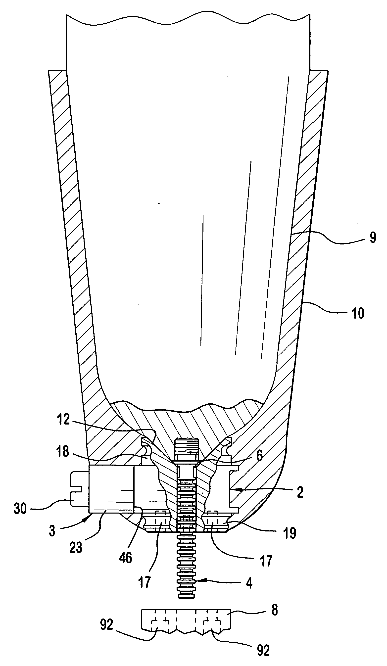
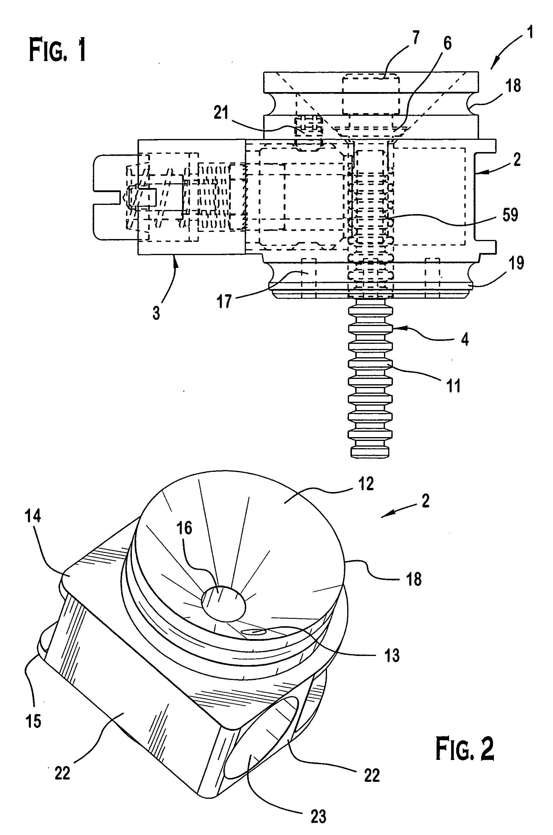
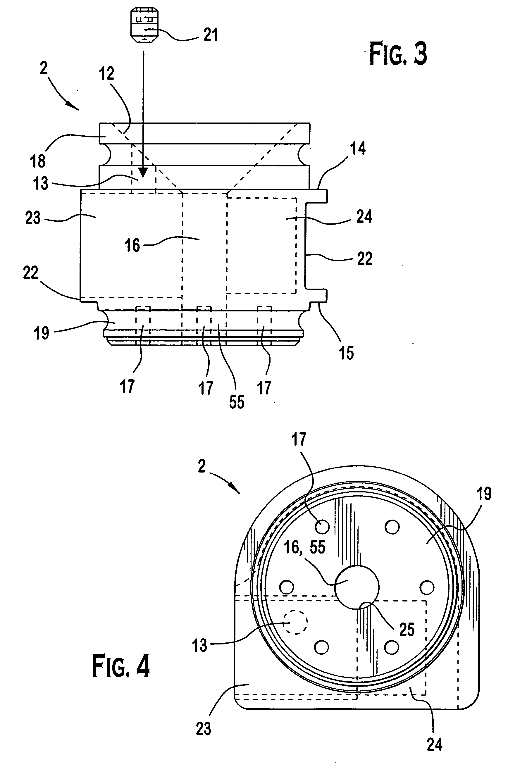
[0027]FIGS. 1-9 show a prosthetic attachment locking device 1. As shown in FIG. 1, the prosthetic attachment locking device I comprises a body 2 with an integral socket adapter 18, a locking mechanism 3, and an attachment pin 4. As shown in FIGS. 2 and 3, the body 2 has side surfaces 22 extending between essentially planar first and second surfaces 14, 15. An axial hole 16 is formed in an approximate center of the body 2 and extends from the first surface 14 to the second surface 15. Extending from one of the side surfaces 22 of the body 2 toward the axial hole 16 is a threaded sleeve receiving recess 23. Adjacent to the sleeve receiving recess 23 is a pawl receiving recess 24. The pawl receiving recess 24 has a diameter smaller than the sleeve receiving recess 23 and extends from the sleeve receiving recess 23 away from the axial hole 16. As shown in FIG. 5, a portion of the sleeve receiving recess 23 and the pawl receiving recess 24 communicate with the axial hole 16 to form a paw...

second embodiment

[0047] The assembly and operation of the prosthetic attachment locking device 60 will now be described in greater detail with reference to FIGS. 10, 11, and 16. As shown in FIG. 10, to assemble the locking mechanism 62, the stem 90 of the bushing 75 is inserted into the axle hole 67 so that the dowel pin 78 is received in the dowel pin hole 73 and the radial hole 77 is aligned with the pawl receiving slot 87. The attachment end 51 of the central axle 50 is inserted into the pawl receiving recess 69 until the attachment end 51 is received in the driving portion 40 and the pawl 52 is received in the radial hole 77. The second face 89 of the sleeve 84 is positioned to abut the side surface 66 of the body 61. The release button 30 is inserted into the button receiving recess 85 so that the screw 35, which is encompassed with the first compression spring 36, is received by the spacer 37 and the second compression spring 38. The screw 35 is secured in the screw receiving recess 54 of the ...


PUM


Abstract

A prosthetic attachment locking device includes a body and a locking mechanism. The body has an axial hole that extends between a first surface and a second surface. The locking mechanism has a central axle with a pawl that communicates with the axial hole. The pawl is displaceable to selectively engage with an attachment pin received in the axial hole. The locking mechanism has a one-way clutch and a ratchet. The one-way clutch and the ratchet are formed to receive the central axle and permit one-way rotation of the pawl.

Description

FIELD OF THE INVENTION [0001] The invention relates to a prosthetic attachment locking device and, more specifically, to a prosthetic attachment locking device with a dual locking mechanism. BACKGROUND OF THE INVENTION [0002] Prosthetic attachment locking devices are used to secure a residual limb, which has been fitted in a socket, to a pylon of a prosthetic limb. The prosthetic attachment locking device generally includes a body having an axial hole extending therethrough and a locking mechanism having a spring loaded reciprocating pawl that cooperates with the axial hole. The socket has a socket adapter that is attached to a first surface of the body by a fastening means that is passed through a set of through-holes in the body. An attachment pin that extends from a liner positioned about the residual limb is inserted through the socket adapter and through the axial hole of the prosthetic attachment locking device until a distal end of the attachment pin is received in the pylon ...

Claims


Application Information

Patent Timeline
IPC IPC(8): A61F2/60A61F2/78
CPCA61F2002/7875A61F2/78
Inventor WAGMAN, CHRIS L.
Owner CASCADE ORTHOPEDIC SUPPLY
Learn More