Clip

a technology of a clip and a clip body is applied in the field of clips to achieve the effect of improving the user experience and reducing the inconvenience of users

Inactive Publication Date: 2005-10-06
LSC COMM US LLC +1
View PDF26 Cites 66 Cited by
  • Summary
  • Abstract
  • Description
  • Claims
  • Application Information

AI Technical Summary

Benefits of technology

[0006] The present invention now provides a clip that addresses the problems identified above. In particular, according to one aspect of the invention a clip includes a clipping part for clipping to an object, and a tab part arranged to extend from the clipping part. The tab part includes a first plastics material and a second rubber material, the rubber material being markable with ink from a conventional pen.

Problems solved by technology

The tab is, however, made of plastic and is only possible to be marked with a suitable water proof marker.
This is inconvenient for the user if they do not have the required marker to hand.

Method used


Image

  • Clip
  • Clip
  • Clip

Examples


first embodiment

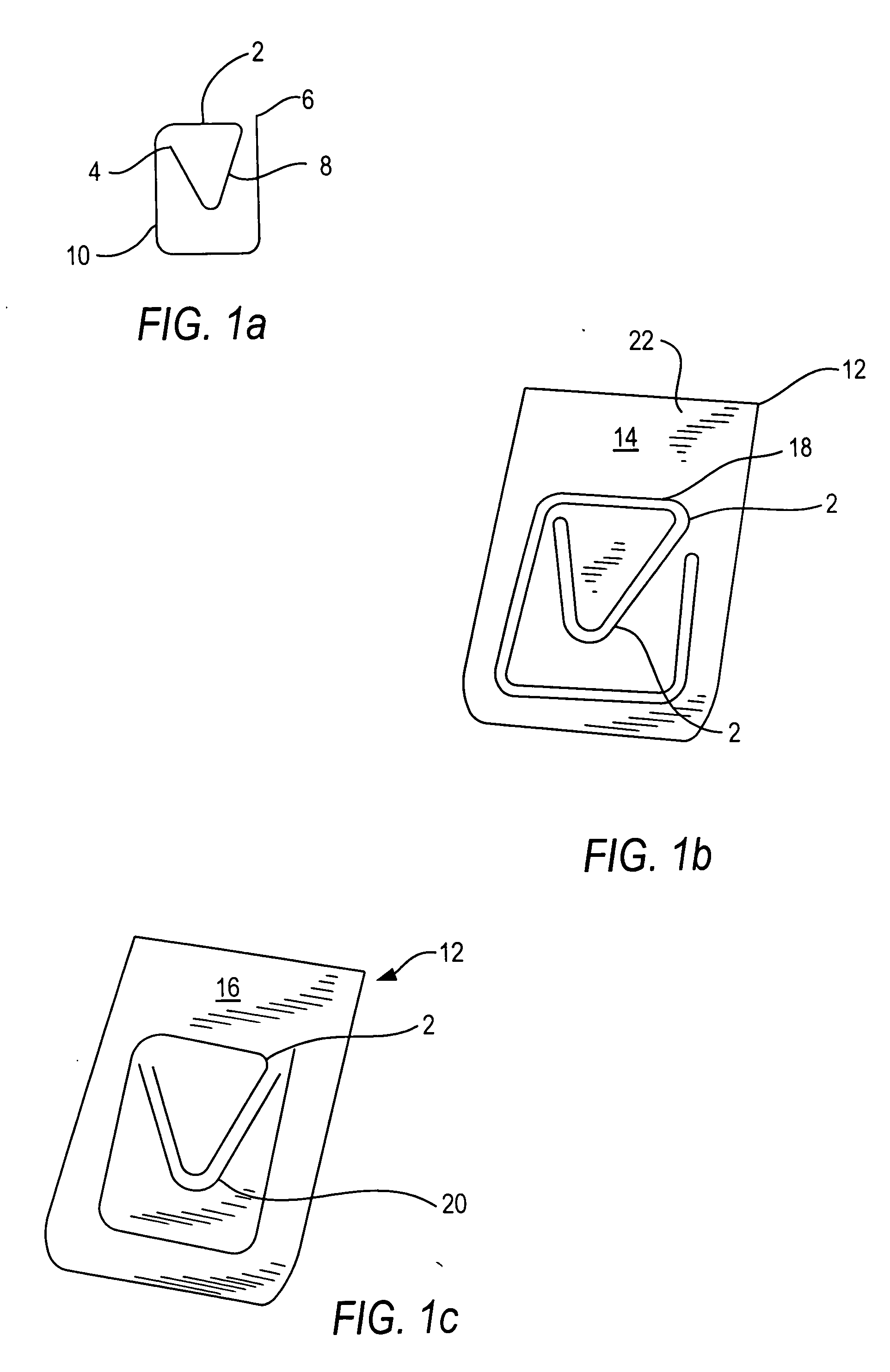
[0041] Reference is now made to FIGS. 1A to 1C which show the present invention. FIG. 1A shows the clipping part 2 of the clip 12 shown in FIGS. 1B and 1C without the writeable material attached thereto. The clipping part is preferably of wire similar to that used by conventional wire paperclips but can be of any suitable material such as plastic or the like.

[0042] The clipping part 2 has a first end 4 and a second end 6. Starting from end 4, the wire adopts a V shaped configuration 8. From the end of the V different to end 4, which extends outwardly from the end portion 4 by a small amount, a substantially rectangular portion 10 is defined which surrounds the V and ends with end portion 6 of the wire. The clipping part 2 shown in FIGS. 1b and 1c is then sandwiched between two layers. FIG. 1b shows the upper surface of the resulting clip 12 while FIG. 1c shows the back surface of the clip construction 12. The clip 12 is defined by sandwiching the wire clip 2 between two layers which...

second embodiment

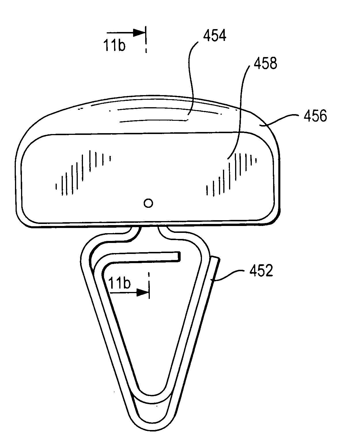
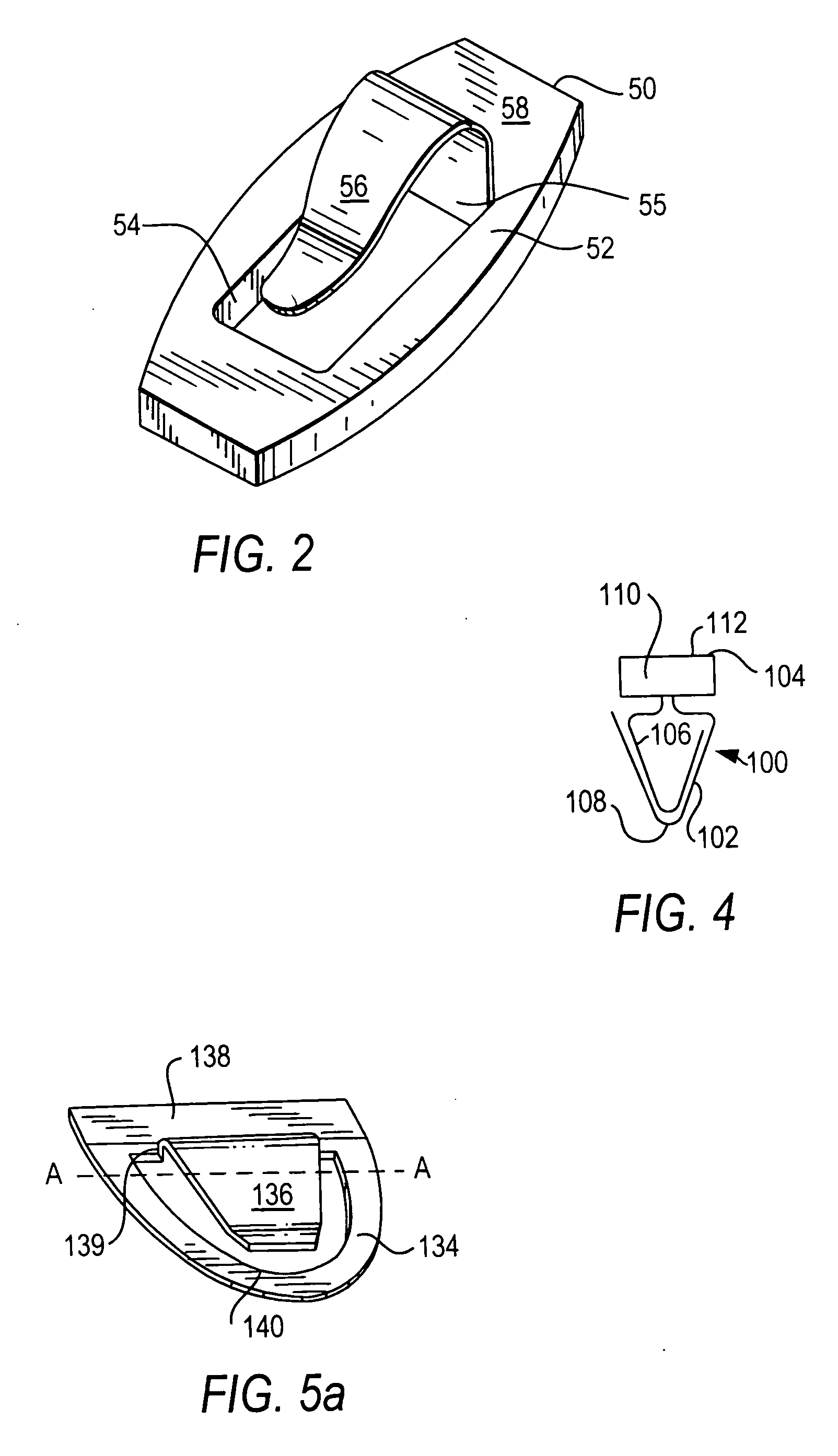
[0051] Reference will now be made to FIG. 2 which shows the present invention. The clip 50 can be made out of any suitable material. In preferred embodiments of the present invention, the clip shown in FIG. 2 is made out of a sandwich material having an external layer or a writeable material with at least one other layer to provide strength. Accordingly, the sandwich may have any one or more of the following materials: paper; plastics; foil; metal; textiles and foil paper. In one embodiment of the invention, the clip is formed from planar material which is hot formed into the desired shape.

[0052] The clip 50 comprises a base 52. The base 52 can take any suitable shape. In the embodiment shown in FIG. 2, the base 52 is generally rectangular in shape with the two long sides thereof being outwardly curved. The base can be rectangular, square, triangular, or indeed any other suitable shape.

[0053] The base 52 has an opening 54 which is generally rectangular in shape. This opening 54 can...


PUM


Abstract

A clip is described that includes a clipping part for clipping to an object, and a tab part arranged to extend from the clipping part. The tab part includes a first plastics material and a second rubber material. This allows the tab part to be marked with ink from a conventional pen.

Description

BACKGROUND ART [0001] The present invention relates to a clip and in particular, stationery clips to be used with paper, card or the like. [0002] Various different clips are well known for holding together a plurality of sheets of paper. Examples include a bull dog clip and the well known basic or common wire paper clip. [0003] Clips have also been proposed for marking a particular page or a particular part of a page. For example, clips in the shape of an arrow can be used to indicate where a signature is needed. Clips are also known which have a tab portion which protrudes beyond the edge of a page or divider to which the clip has been attached. This allows a particular page or section to be easily referenced. The tab is, however, made of plastic and is only possible to be marked with a suitable water proof marker. This is inconvenient for the user if they do not have the required marker to hand. [0004] It has also been proposed to provide clips with advertising across one of the c...

Claims


Application Information

Patent Timeline
Patent Type & Authority Applications(United States)
IPC IPC(8): B42F1/02B42F21/06G09F3/06
CPCB42F1/02Y10T24/20Y10T24/202
Inventor GROCH, HANS-WERNERSEIFFARTH, STEFFEN
Owner LSC COMM US LLC
Why Eureka
Try Eureka