Method for forming carbon fiber pipe and die thereof

A forming method and carbon fiber technology, applied in the forming method of carbon fiber pipes and the field of molds, can solve the problems of layering, difficult mold closing, low production efficiency, etc., and achieve good quality stability, uniform product wall thickness, and low manufacturing cost Effect

Active Publication Date: 2012-06-13
NINGBO INST OF MATERIALS TECH & ENG CHINESE ACADEMY OF SCI
View PDF4 Cites 44 Cited by
  • Summary
  • Abstract
  • Description
  • Claims
  • Application Information

AI Technical Summary

Problems solved by technology

But when the pipe to be manufactured is an irregular pipe, such as with grooves, this method has the following disadvantages: (1) Difficulty in mold clamping and low production efficiency; (2) The molding pressure is limited, and the composite material layer of the product is easy Defects such as delamination and air bubbles lead to unstable product quality and high scrap rate

Method used


Image

  • Method for forming carbon fiber pipe and die thereof
  • Method for forming carbon fiber pipe and die thereof
  • Method for forming carbon fiber pipe and die thereof

Examples


Embodiment 1

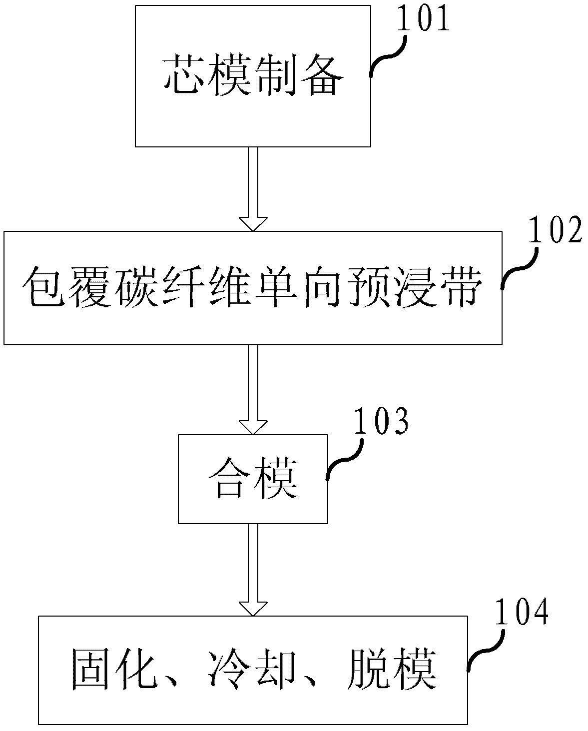
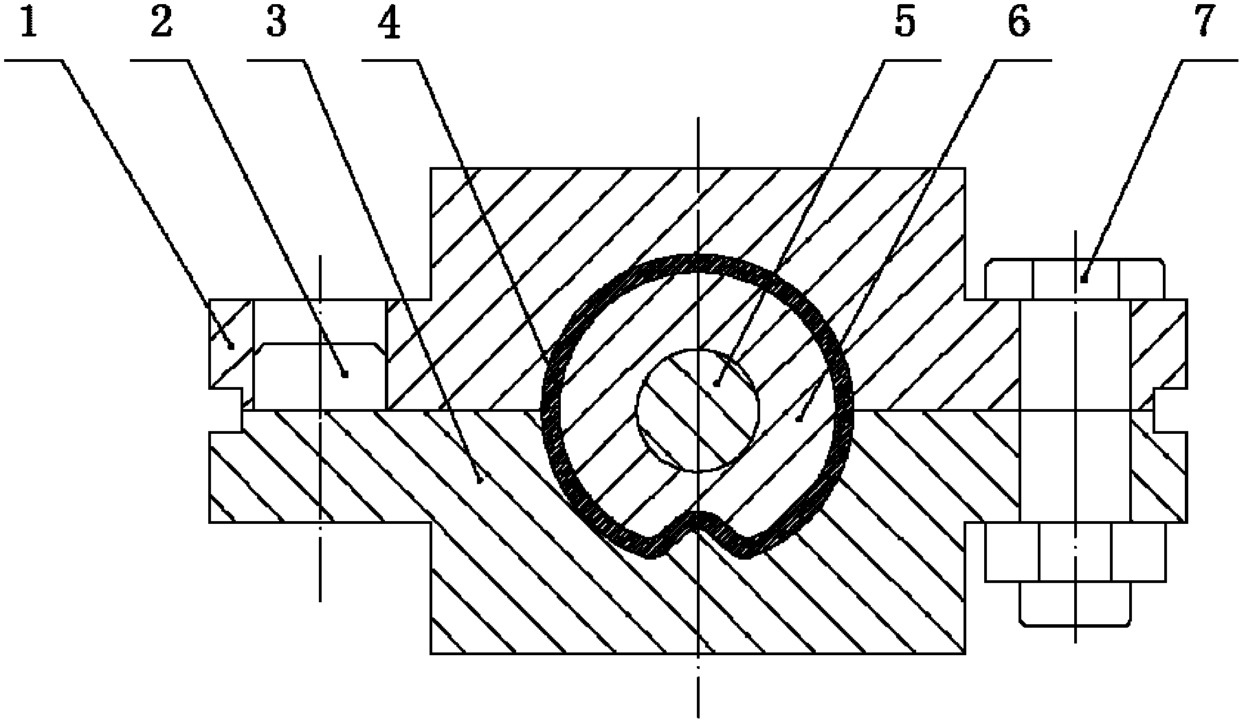
[0067] Adopting the above-mentioned carbon fiber pipe forming method to manufacture an outer diameter of φ28mm, a wall thickness of 1.5mm, and a length of 280mm is a grooved carbon fiber foot tube of a photographic tripod. Make a mandrel with a metal mandrel diameter of φ11 and a rubber material thickness of 7mm. The metal mandrel and the rubber are firmly bonded with a special adhesive based on silicone rubber material. Cut 8 layers of T7000SC-12K carbon fiber unidirectional prepreg tape, and the fiber angles from the first layer to the eighth layer are 0°, 45°, -45°, 0°, 15°, -15°, 5°, - 5°, each layer of the cut carbon fiber unidirectional prepreg tape is manually wrapped on the mandrel according to the angle. Align the core mold with the female mold and fasten it with bolts. Put the mold into the oven, after the carbon fiber unidirectional prepreg tape is cured, it is cooled to below 60°C with the furnace, and the mold is demoulded to form the required carbon fiber legs ...

Embodiment 2

[0070] The above-mentioned carbon fiber pipe forming method is used to manufacture the carbon fiber foot pipe of the photography tripod. The main difference from the above-mentioned Example 1 is that the diameter of the metal mandrel is increased to φ11.5, and the thickness of the rubber material is still 7mm; the carbon fiber unidirectional prepreg tape is paved with a 6-layer structure, and each fiber from the first layer to the sixth layer The cladding angles are 0°, 45°, -45°, 0°, 5°, -5°, and other materials, processes and parameters remain unchanged, and the carbon fiber legs of the photography tripod are made. After testing, the surface and internal quality of the workpiece are the same as in Example 1, that is, the surface is smooth, free of air bubbles, and there is no crispness or delamination inside; meanwhile, the longitudinal strength of the workpiece is basically equal, but the transverse strength is slightly reduced.


PUM

PropertyMeasurementUnit
tensile strengthaaaaaaaaaa
thicknessaaaaaaaaaa
thicknessaaaaaaaaaa

Abstract

The invention discloses the technical field of carbon fiber composite materials, and discloses a method for forming a carbon fiber pipe. The method comprises the following steps of: preparing a core mould, namely preparing the core mould for wrapping carbon fiber one-way preimpregnation belts, wherein the core mould comprises a metal core rod and a rubber material wrapping the metal core rod; paving and coating the carbon fiber one-way preimpregnation belts, namely after coating a release agent on the surface of the core mould, paving and coating a plurality of layers of carbon fiber one-way preimpregnation belts according to different angles; closing the die, namely positioning the core mould in which the carbon fiber one-way preimpregnation belts are paved and coated and putting into a female die, closing the die, and fastening; and curing, cooling and demoulding, namely putting the die which is closed into a drying oven, curing, cooling with a furnace, and demoulding to form the required finished piece. The method for forming the carbon fiber pipe has the advantages of simple process, high production efficiency, low manufacturing cost, uniform wall thickness of the product, high quality and stability and the like.

Description

technical field [0001] The invention relates to the technical field of carbon fiber composite materials, in particular to a method for forming a carbon fiber pipe and a mold thereof. Background technique [0002] Carbon fiber is a microcrystalline graphite material obtained by carbonizing and graphitizing organic fibers. The microstructure of carbon fiber is similar to artificial graphite, which is a turbostratic graphite structure. Carbon fiber is a new material with excellent mechanical properties. The tensile strength of carbon fiber resin composite materials is generally above 3500Mpa, which is 7 to 9 times that of steel, and the tensile elastic modulus is 230-430Gpa. Therefore, the ratio of the strength of the material to its density can reach more than 2000Mpa. [0003] Aluminum alloy is a kind of non-ferrous metal structural material widely used in industry. It has high shaping and good corrosion resistance, and can be made into various pipes, profiles and plates. ...

Claims


Application Information

Patent Timeline
Patent Type & Authority Applications(China)
IPC IPC(8): B29C70/38B29C33/38
Inventor 陈刚杨现伟范欣愉
Owner NINGBO INST OF MATERIALS TECH & ENG CHINESE ACADEMY OF SCI
Why Eureka
Try Eureka