Composite structure plastic faucet main body and manufacturing method thereof

A composite structure and faucet technology, applied in the field of faucets, can solve problems such as poor product structure stability, long production process, and many processes, and achieve the effects of easy mold opening and closing, simple internal structure, and simple production process

Inactive Publication Date: 2022-08-05
姚平
View PDF0 Cites 0 Cited by
  • Summary
  • Abstract
  • Description
  • Claims
  • Application Information

AI Technical Summary

Problems solved by technology

[0002] Most of the faucets on the existing market are traditionally made of copper alloy. In recent years, stainless steel, zinc alloy and other materials have also appeared. As the price of metals continues to rise, the price of faucets made of traditional materials is also rising. Continuously strengthened, faucets made of traditional materials can no longer meet people's pursuit of a healthy life
However, traditional material faucets still have many irreversible problems such as long production process, many processes, (sand core, casting, machining, grinding, polishing, surface treatment, etc.) production cycle is too long, and the loss between processes is large.
Under the growing market demand, plastic environmental protection faucets came into being, but the methods of making plastic faucets on the market still have many deficiencies in the specific implementation of manufacturing: 1. The structure is complex, the yield rate is low, and the defective rate is high; 2. .The production process is complex and cumbersome, and the production cycle is long; 3. The product structure is poor in stability and not durable; 4. Due to the structural problems of the product, the appearance innovation of the product is limited, and there are shortcomings such as old appearance

Method used


Image

  • Composite structure plastic faucet main body and manufacturing method thereof
  • Composite structure plastic faucet main body and manufacturing method thereof
  • Composite structure plastic faucet main body and manufacturing method thereof

Examples


Embodiment Construction

[0032] The technical solutions in the embodiments of the present invention will be clearly and completely described below with reference to the accompanying drawings in the embodiments of the present invention. Obviously, the described embodiments are only a part of the embodiments of the present invention, but not all of the embodiments. Based on the embodiments of the present invention, all other embodiments obtained by those of ordinary skill in the art without creative efforts shall fall within the protection scope of the present invention.

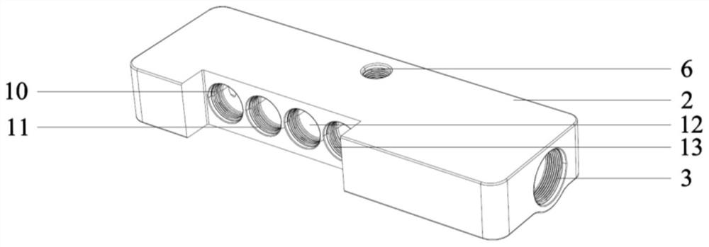
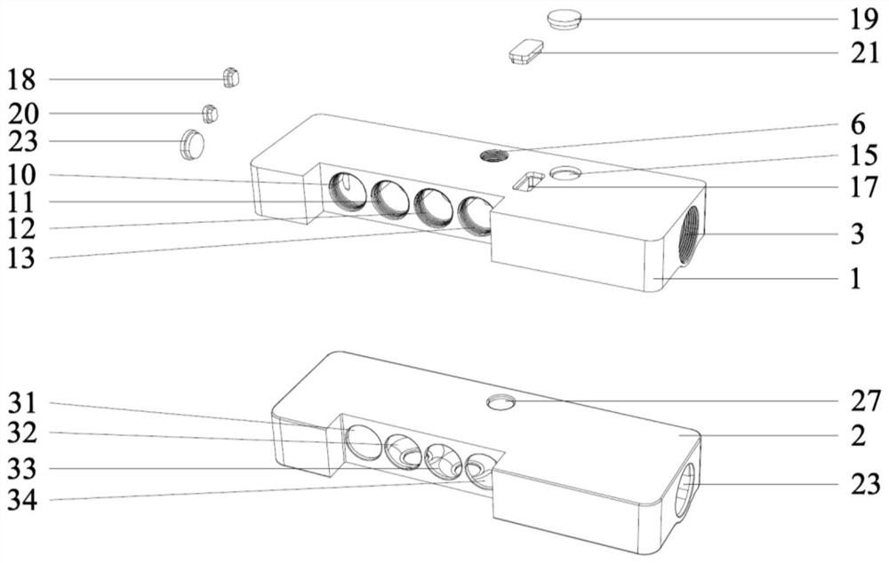
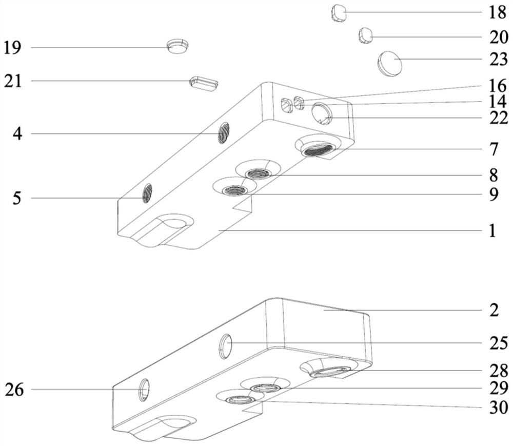
[0033] like Figure 1 to Figure 7A composite structure plastic faucet body of the present invention is shown, including a plastic inner core body 1 and a plastic wrapping layer 2 wrapped on the outer side of the plastic inner core body 1, and a water control valve core is installed on the right side of the plastic inner core body 1 Hole 3, the rear side of the plastic inner core body 1 is provided with a cold water connector mounting ...


PUM


Abstract

The composite structure plastic faucet body comprises a plastic inner core body and a plastic wrapping layer wrapping the outer side of the plastic inner core body, and a first transverse open caisson channel communicating with a cold water inlet hole is formed in the rear side of the plastic inner core body; the upper side of the plastic inner core body is provided with a first longitudinal open caisson channel communicating with the first transverse open caisson channel and the cold water inlet channel, and the rear side of the plastic inner core body is provided with a second transverse open caisson channel communicating with the mixed water inlet hole. The upper side of the plastic inner core body is provided with a second longitudinal open caisson channel communicating with the second transverse open caisson channel and the mixed water passing channel, and the outer side of the first transverse open caisson channel is covered with a first open caisson cover. The open caisson type structure is arranged in the plastic inner core body, so that an injection mold of the plastic inner core body is easy to manufacture, the structure is high in adaptability to appearance, the production process is simple, injection molding is smooth, and a product obtained after injection molding is good in stability, firm and durable.

Description

technical field [0001] The invention relates to the technical field of faucets, in particular to a composite structure plastic faucet body and a manufacturing method thereof. Background technique [0002] Most of the faucets on the existing market are traditionally made of copper alloys. In recent years, stainless steel, zinc alloys and other materials have also appeared. As the price of metals continues to rise, the prices of traditional faucets are also rising. With continuous strengthening, traditional faucets can no longer meet people's pursuit of healthy life. The traditional material faucet still has many irreversible problems such as long production process, many processes, (sand core, casting, machining, grinding, polishing, surface treatment and other processes) production cycle is too long and the loss between processes is large. Under the growing market demand, plastic environmental protection faucets have emerged as the times require, but there are still many de...

Claims


Application Information

Patent Timeline
Patent Type & Authority Applications(China)
IPC IPC(8): F16K11/22F16K27/00B29C69/00
CPCF16K11/22F16K27/00B29C69/00Y02A20/411
Inventor 姚平
Owner 姚平
Why Eureka
Try Eureka