I-joist web hole insert

a technology for inserting web holes and joists, which is applied to joists, girders, constructions, etc., can solve the problems of limited web area for cutting web holes, unable to meet the needs of construction workers, etc., and achieves the effect of convenient installation and easy handling

Inactive Publication Date: 2005-10-06
DAVIS JOHN D
View PDF13 Cites 10 Cited by
  • Summary
  • Abstract
  • Description
  • Claims
  • Application Information

AI Technical Summary

Benefits of technology

[0008] The insert is an easy to handle and easy installable element that in combination with standardized cut web holes

Problems solved by technology

Irrespective a proper cutting, the web hole may still suffer damage during the consecutive installation of pipes, tubes, and cabling at the construction site.
In an installed I-joist, web area is limited for cutting web holes.
As a common result, a multitude of pipes, tubes

Method used


Image

  • I-joist web hole insert
  • I-joist web hole insert
  • I-joist web hole insert

Examples


Embodiment Construction

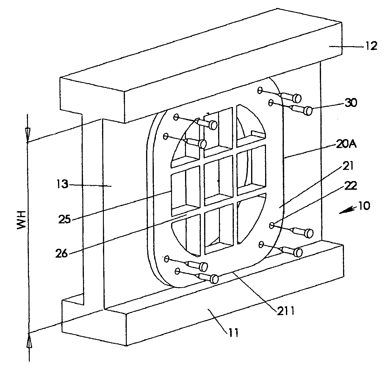
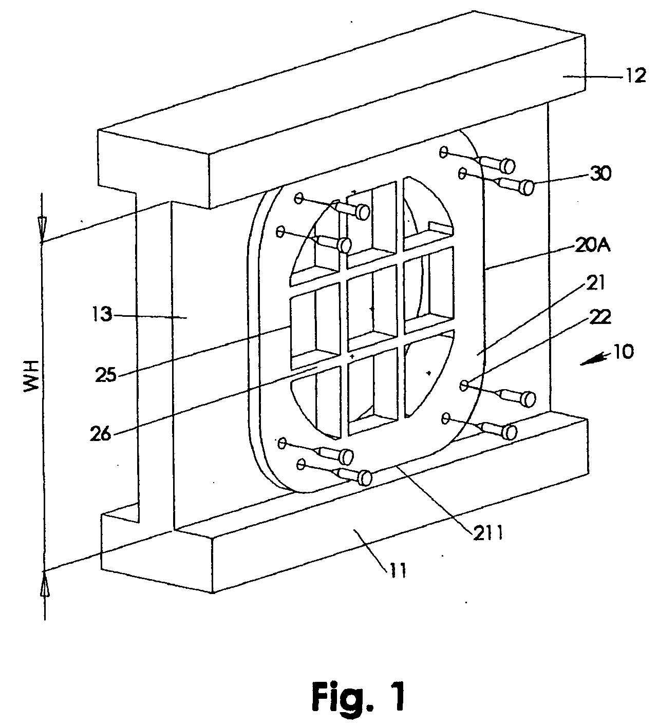
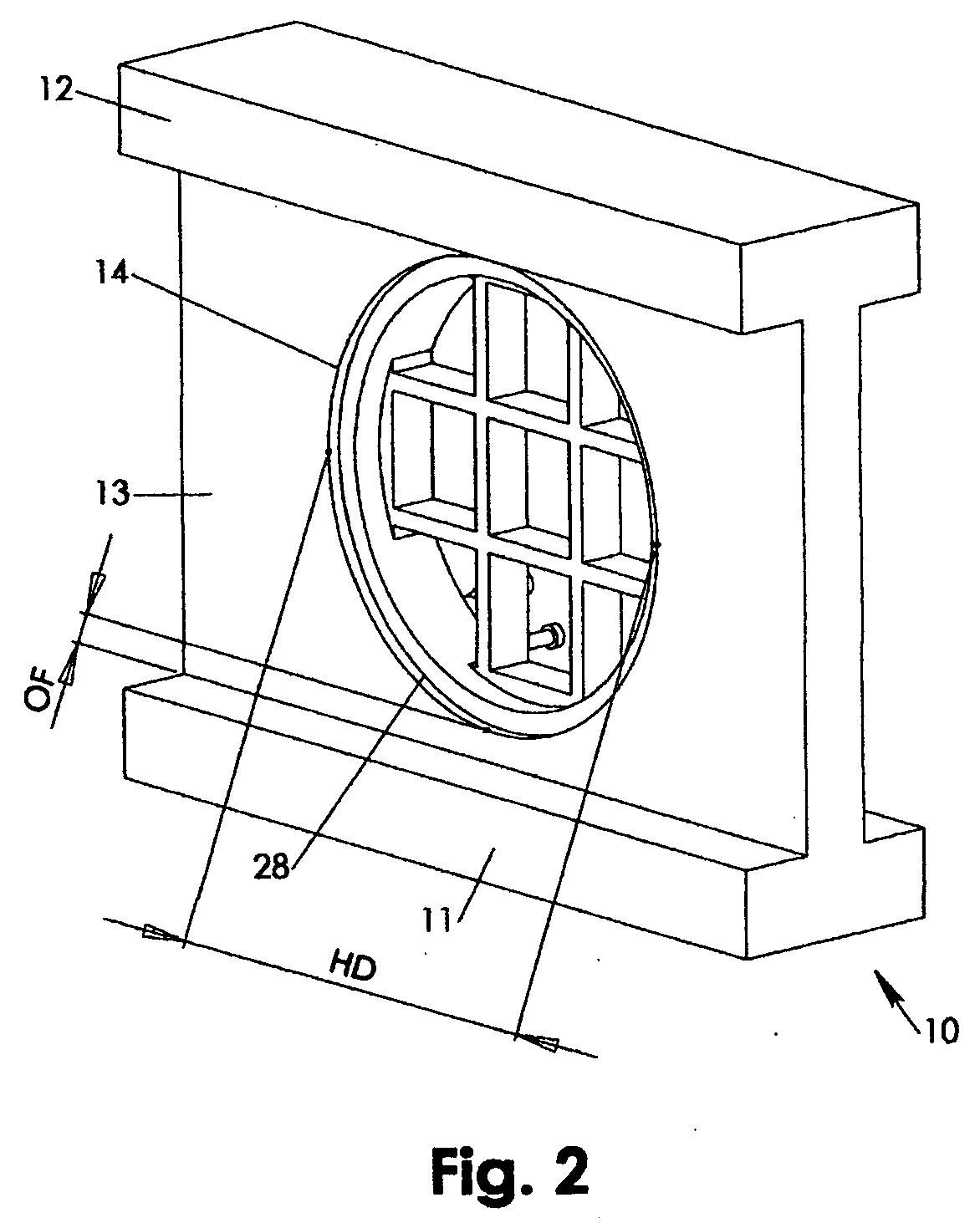
[0019] An I-joist 10, a portion of which is depicted in the Figures, may be combined with an insert 20A-20F in various configurations and eventual combination with other structures, such as attachment pins 30 as in FIG. 1, thread flange 40A, 40B as in FIGS. 5-7 and / or an I-joist support 50 as in FIG. 10. Attachment pins 30 may be nails, screws and the like well known in the field of architectural construction. The insert 20A-20F provides at least one cutout contour 25 for guiding at least one of a pipe, a tube, and a cable through the web hole 13 without direct contact between the web hole 13 and said at least one of a pipe, a tube and a cable, such that the web hole 13 edges are protected against inadvertent damaging.

[0020] According to FIG. 1, a first exemplary embodiment of an insert 20A may have a flange 21 for snuggly contacting the web portion 13 of I-joist 10. The flange 21 may have a circumferential contour that at least partially complies with at least one of the bottom ch...


PUM


Abstract

An insert for I-joist web holes provides support and separation for piping, tubing and/or cabling guided through the installed I-joist's web. At the same time, the insert protects the web hole against destructive forces commonly related to the installation process and/or gravitational loads of piping, tubing and/or cabling.

Description

PRIORITY CLAIM [0001] The present invention claims priority to U.S. Provisional Application of the same title and inventor, Application No. 60 / 552,326, filed Mar. 10, 2004, which is hereby incorporated by reference. CROSS REFERENCES [0002] The present invention cross references and incorporates by reference U.S. Pat. No. 6,857,831, filed Feb. 27, 2004, titled “I-joist Hole Cutting Apparatus” and U.S. application Ser. No. 10 / 410,505, filed Apr. 8, 2003, titled “Buckling Opposing Support for I-joist”, both of the same inventor as in the present application.FIELD OF INVENTION [0003] The present invention relates to web inserts for I-joists. More particularly, the present invention relates to web inserts for supporting tubing, piping, cables and the like commonly installed across web holes of wooden I-joists in architectural constructions. BACKGROUND OF INVENTION [0004] I-joists referred in the following and in the context with the present invention are made from wood and wood like mate...

Claims


Application Information

Patent Timeline
IPC IPC(8): E04C2/52E04C3/14E04G23/02
CPCE04G23/0218E04C3/14E04G23/0244
Inventor DAVIS, JOHN D.
Owner DAVIS JOHN D
Why Eureka
Try Eureka