Photovoltaic power generation system

Inactive Publication Date: 2005-10-06
KYOCERA CORP
View PDF6 Cites 90 Cited by
  • Summary
  • Abstract
  • Description
  • Claims
  • Application Information

AI Technical Summary

Benefits of technology

[0069] According to this arrangement, the air-inflow blocking member is disposed in the vicinity of the space region under the solar cell module, thereby reducing or eliminating the air flow into the space region. Thus, a force of wind or the like to lift up the solar cell module may be decreased so that a shortage of weight is offset in the arrangement wherein the solar cell module is held at place by way of the combined weights of the first and second racks of the solar cell module. As a result, the solar cell modules and the like may be supported in a manner to ensure that the solar cell modules and the like are not blown away by the negative pressure load such as wind.
[0070] If an arrangement is made such that the air-inflow blocking member is provided with a slant plane for guiding an air flow toward the slant plane to flow over an upper side of th

Problems solved by technology

Unfortunately, the aforementioned prior art has a drawback that the foundation works extends the period of works.
The holes detrimentally allow the invasion of rain water therethrough so that the installation surface is damaged.
As a result, the life of the installation surface is shortened.
What is more, the system includes a large number of components which take much time to assemble.
In addition, the individual components are heavy so that the conveyance of the members up to the roof or the carriage of the members involves potential danger.
In this case, the site where the anchors are buried does not necessarily provide such conditions as to permit the solar cell modules to be so directed as to provide a substantial power output.
Hence, the solar cell modules may not be installed in an optimum di

Method used


Image

  • Photovoltaic power generation system
  • Photovoltaic power generation system
  • Photovoltaic power generation system

Examples


Example

[0121] A photovoltaic power generation system according to one embodiment of the invention will hereinbelow be described in details with reference to the accompanying schematic drawings.

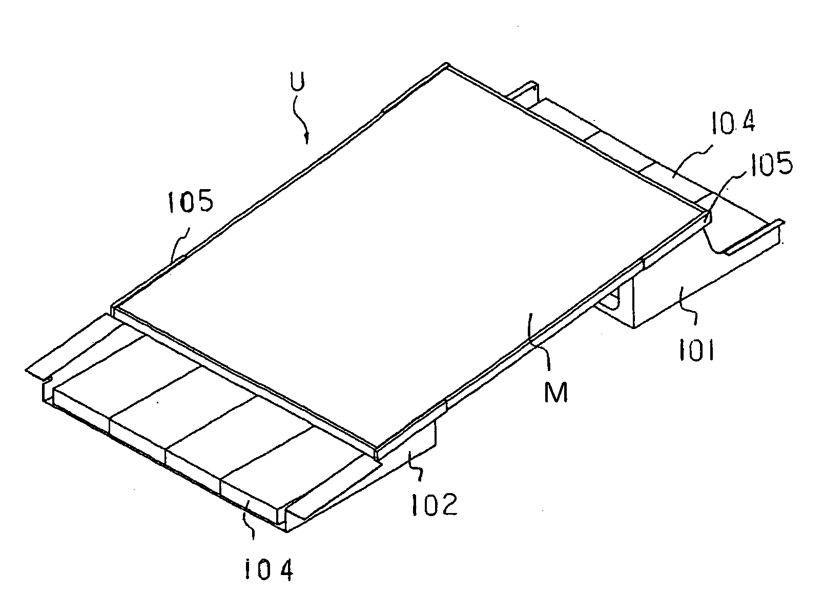
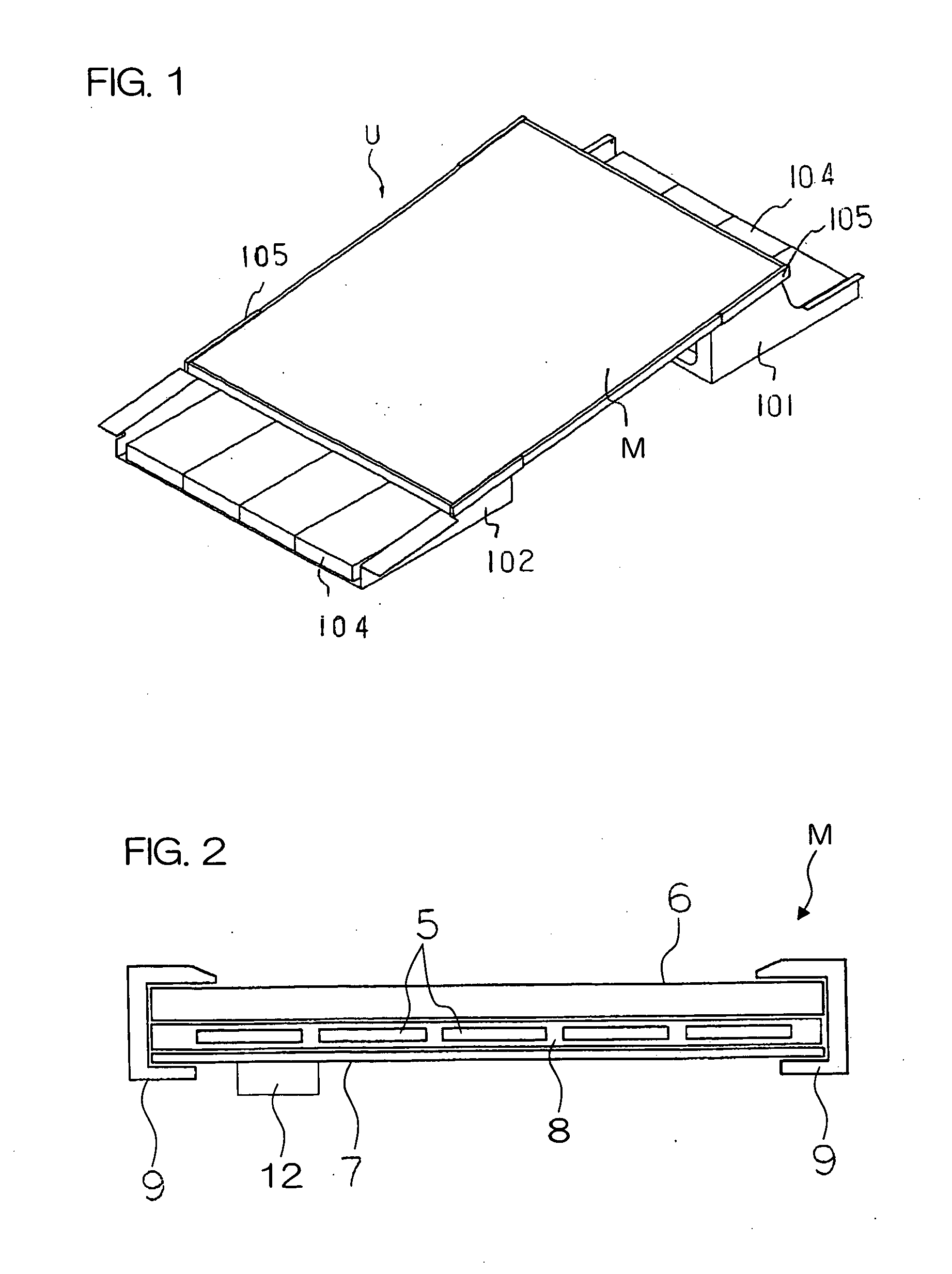
[0122]FIG. 1 is a perspective view showing a solar cell unit U.

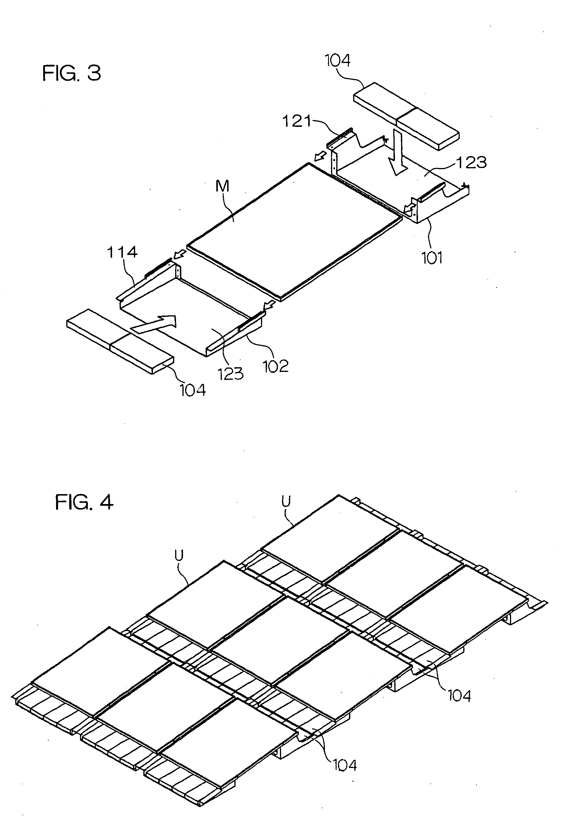
[0123] The solar cell unit U comprises: a solar cell module M, an upper side rack 101 and a lower side rack 102, the upper and lower side racks serving to support the solar cell module M in an inclined position. The upper side rack 101 is equivalent to a “first rack”, whereas the lower side rack 102 is equivalent to a “second rack”.

[0124] The solar cell unit further employs a weight 104 for preventing the upper side rack 101 and the lower side rack 102 from being displaced from their installation places.

[0125] The weight 104 is, for example, a concrete block or a metal block such as of iron. FIG. 1 illustrates an example using four blocks on each side. However, one piece of the weight itself may be made heavier to reduce the division ...


PUM


Abstract

A photovoltaic power generation system comprises: a rectangular- or square-shaped solar cell module M including one or more solar cell elements 5; first and second racks 101, 102 assembled to opposite sides of the solar cell module M, respectively; and a weight member 104 disposed at a predetermined place of the first rack 101 and/or the second rack 102. The system is adapted to be held to place by means of the weight member 104 in order that the solar cell module M may not be blown away by the wind. Therefore, the system may be used simply by placing the system on an installation surface such as a flat roof. This results in the reduction of the number of assembly steps involved in installation works and the reduction of fabrication costs and time. Thus is achieved cost reduction.

Description

BACKGROUND OF THE INVENTION [0001] 1. Field of the Invention [0002] The present invention relates to a photovoltaic power generation system for generating photovoltaic power by using solar cell modules, and more particularly to a photovoltaic power generation system adapted to be rack mounted on a horizontal installation surface such as a flat roof. [0003] The “solar cell module” means herein a panel-shaped device including one or more solar cell elements electrically interconnected in series and / or in parallel. [0004] A unit adapted to generate power by using the solar cell module(s) is referred to as a “solar cell unit”. [0005] A system adapted to output the photovoltaic power by using one solar cell unit or an assembly of the above solar cell units interconnected is referred to as a “photovoltaic power generation system”. [0006] 2. Description of the Related Art [0007] Recently, the photovoltaic power generation systems have come into wide use, the system including the solar cell...

Claims


Application Information

Patent Timeline
IPC IPC(8): H01L25/00H01L31/042H01L31/048
CPCF24J2/4638F24J2/5235F24J2/5239F24J2/526F24J2002/5292H02S20/24Y02B10/20Y02E10/47Y02E10/50H02S20/00Y02B10/12F24S25/15F24S25/16F24S25/65F24S40/85F24S2025/02Y02B10/10
Inventor MASUDA, HIROTONAKAGAWA, KEIJI
Owner KYOCERA CORP
Why Eureka
Try Eureka