System of controlling a sliding member for a vehicle

a technology of sliding member and sliding member, which is applied in the direction of motor/generator/converter stopper, electric controller, dynamo-electric converter control, etc., can solve the problems of actual position of sliding roof deviating, rain leaking, and noise generated by sliding roof or motor

Active Publication Date: 2005-10-06
HONDA MOTOR CO LTD +1
View PDF5 Cites 9 Cited by
  • Summary
  • Abstract
  • Description
  • Claims
  • Application Information

AI Technical Summary

Benefits of technology

[0019] The system described above provides reliable detection of displacement of the sliding member.

Problems solved by technology

The technique disclosed in JP2001-180283 has a drawback that a sliding roof creates colliding noise or a motor generates uncomfortable noise such as beat noise.
However, it may occur that an actual position of sliding roof deviates from a theoretical position defined in a control system in the form of pulse counts.
If no correction is imposed on this type of deviation, an anomaly such as erroneous creation of a gap between the sliding roof and the periphery of opening may occur, resulting in rain leaking.
Accordingly, even if the method described above is introduced for improving the technique disclosed in the patent document, there still remains a problem to be solved that displacement of sliding roof needs to be reliably detected so as to implement appropriate control for the position of sliding roof.

Method used


Image

  • System of controlling a sliding member for a vehicle
  • System of controlling a sliding member for a vehicle
  • System of controlling a sliding member for a vehicle

Examples


first embodiment

a. First Embodiment

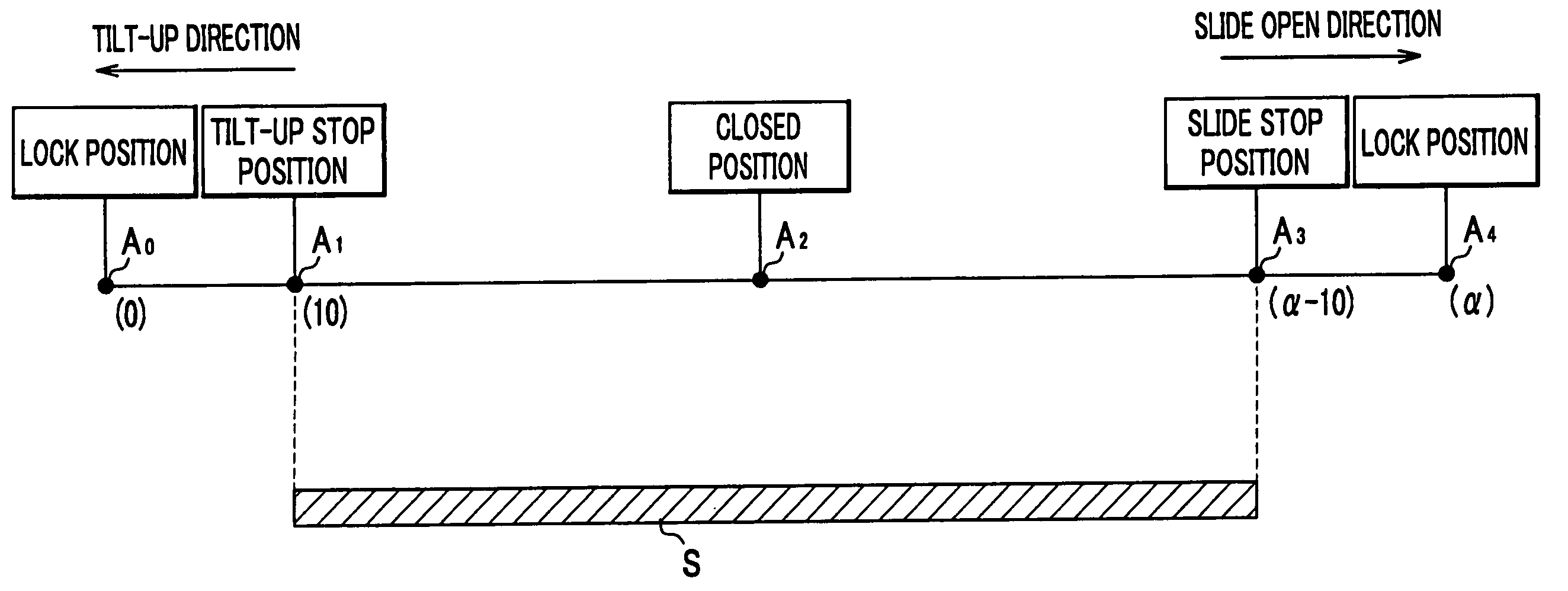
[0035] The counting device 4 counts up or down pulses relative to a lock position as described above. In FIGS. 4A to 4C, the counting device 4 counts pulses, selecting a lock position A0 (pulse count “0”) as a reference point, which corresponds to a tilted position. The other lock position A4, which corresponds to an open position, is given a pulse count α. A closed position A2 is located between the lock positions A0 and A4.

[0036] If positions for stopping the sliding roof 13 are adapted to coincide with the lock positions A0 and A4, colliding noise may likely occur as described above. In order to overcome this problem, the present invention introduces a tilt-up stop position A1, which is positioned slightly short of the lock position A0, and a slide stop position A3, which is positioned slightly short of the lock position A4. Furthermore, the present invention introduces an operation range S for the sliding roof 13, which covers the position A1 to the position ...

second embodiment

b. Second Embodiment

[0044] As shown in FIG. 5, pulse counts are assigned for the positions of a sliding roof 13 in a similar manner as that of the embodiment 1.

[0045] Detecting an overload for a motor 2 when the sliding roof 13 comes to a stop, a control device 5 automatically selects a manual mode for the sliding roof 13. If the sliding roof 13 normally stops during a subsequent movement, the control device 5 automatically restores an automatic mode for the sliding member 13. In this way, it is possible to distinguish one type of irregular discontinuation due to an obstacle between the sliding member 13 and an opening 12 from the other type caused by displacement of the sliding member 13. This results in reliable detection of displacement of the sliding roof 13.

[0046] When not only the sliding roof 13 repeats irregular discontinuation of its movement due to overloading of the motor 2 at a position twice or more, but also pulse counts counted by a counting device 4 fall in a prede...


PUM


Abstract

A system of controlling a sliding member for a vehicle includes a motor, a pulse generating device, a counting device and a control device. The system has a range for movement of the sliding member between a position short of a first lock position and a position short of a second lock position. Also, the system has an error range within the range for movement of the sliding member and memorizes in advance a range of pulse count representative of the error range. If a pulse count counted by the counting device falls within the range of pulse count when the sliding member discontinues movement due to detection of an overload of the motor, the system resets a pulse count counted by the counting device at one of the first and second lock positions.

Description

BACKGROUND OF THE INVENTION [0001] The present invention relates to a system of controlling a sliding member for a vehicle, which is used for a sliding roof in a sunroof apparatus, for example. [0002] A sliding roof has been used for a vehicle, which is mounted for the purpose of controlling the temperature of its cabin or providing a feeling of freedom for its passengers. This sliding roof is usually driven by a motor, which allows not only its sliding movement between open and closed positions, but also its tilting movement by lifting its end portion at this closed position. [0003] A technique for controlling a sliding roof is disclosed, which selects mechanically locked positions at its open position and tilted position as reference positions, where the sliding roof discontinues its movement as a result of mechanical contact to a periphery of opening. Related arts are disclosed in Japanese Published Patent Application 2001-180283. [0004] The technique disclosed in JP2001-180283 h...

Claims


Application Information

Patent Timeline
Patent Type & Authority Applications(United States)
IPC IPC(8): H02P3/00
CPCB60J7/0573
Inventor UEHARA, TATSUAKIHONJO, YUKINORO, YOSHIKI
Owner HONDA MOTOR CO LTD
Why Eureka
Try Eureka