Image-forming device

a technology of forming device and image, which is applied in the field of image forming device, can solve the problems of reducing the quality of gray image, affecting the quality of image, and affecting the quality of imag

Inactive Publication Date: 2005-10-06
BROTHER KOGYO KK
View PDF9 Cites 18 Cited by
  • Summary
  • Abstract
  • Description
  • Claims
  • Application Information

AI Technical Summary

Benefits of technology

[0024] According to another aspect, the present invention provides a storage medium storing a program readable by a computer, the program including: a program of creating density adjustment data that indicates usage amounts of a plurality of different color materials to be used to form an image in a predetermined color at each density; a program of detecting a deviation quantity of the predetermined color in the density adjustment data at each of at least one density; a program of setting, based

Problems solved by technology

However, the three composed amounts will likely get out of balance when forming gray at a low density.
When only cyan is used, for example, an area intended to be light gray will erroneously ap

Method used


Image

  • Image-forming device
  • Image-forming device
  • Image-forming device

Examples


first embodiment

[0050] First, an inkjet printer 1 according to a first embodiment of the present invention will be described with reference to FIG. 1(a) to FIG. 5(b).

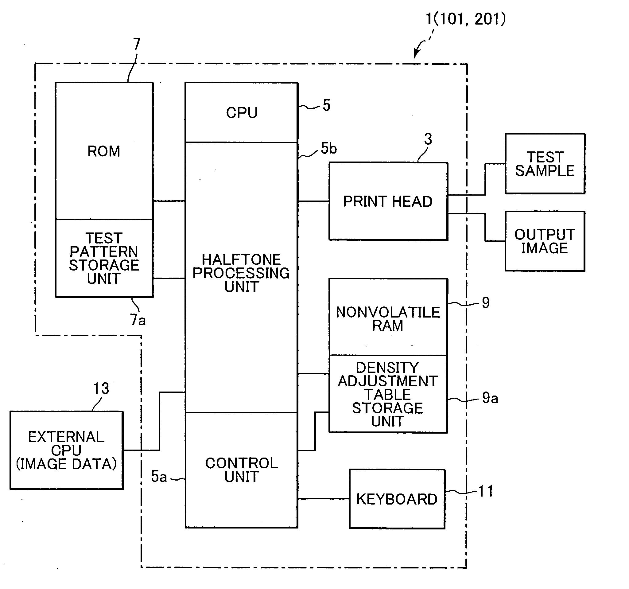
[0051] First, the structure of the inkjet printer 1 will be described with reference to FIG. 1.

[0052] The printer 1 includes: a print head 3; a central processing unit (CPU) 5; a ROM 7; a nonvolatile RAM 9; and a keyboard 11. The central processing unit (CPU) 5 is connected to an external CPU 13, which is provided in a personal computer or the like, and is capable of receiving data from the external CPU 13.

[0053] Although not shown in the drawings, the print head 3 includes nozzles that eject a cyan (C) ink, nozzles that eject a magenta (M) ink, nozzles that eject a yellow (Y) ink, and nozzles that eject a black (K) ink. The print head 3 forms color images by superimposing images in these four colors of ink. It is noted that the print head 3 forms gray images by superimposing ink in the four colors of cyan, magenta, yellow, and blac...

second embodiment

[0138] Next, a printer 101 according to a second embodiment of the present invention will be described with reference to FIG. 1 and FIGS. 6-14.

[0139] While the structure and operations of the printer 101 according to the second embodiment are essentially identical to those of the printer 1 in the first embodiment except that the printer 101 executes the density adjustment table creating process of FIGS. 6-14 instead of executing the density adjustment table creating process of FIGS. 3-5(a).

[0140] The density adjustment table creating process according to the second embodiment will be described below with reference to FIGS. 6-14.

[0141] As shown in FIG. 6, the density adjustment table creating process of the second embodiment is the same as that of the first embodiment of FIG. 3 except that processes of S430-S450 are executed instead of the process of S130 (FIG. 3) and processes of S470 and S480 are executed instead of the process of S150 (FIG. 3).

[0142] In S430, in the same manne...

third embodiment

[0190] Next, a printer 201 according to a third embodiment of the present invention will be described with reference to FIG. 1 and FIGS. 15(a)-15(c).

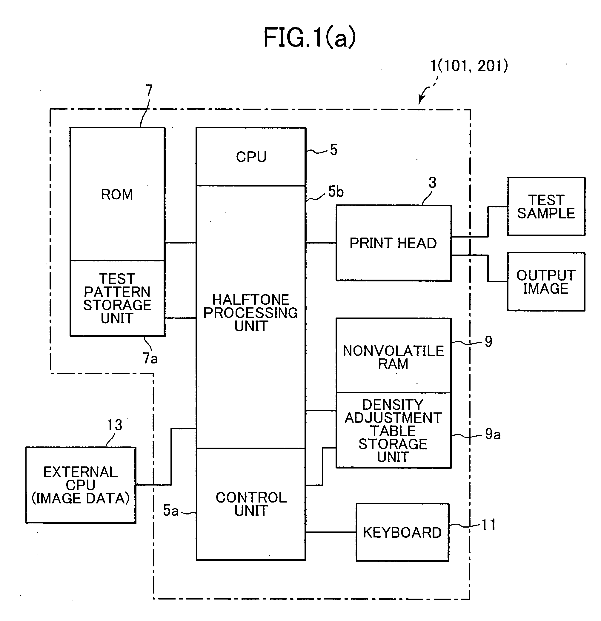
[0191] The structure and operation of the printer 201 according to the third embodiment is essentially identical to those of the printer 1 according to the first embodiment except that another density adjustment table Tdensity′ shown in FIG. 15(a) is stored in the density adjustment table storage unit 9a instead of the density adjustment table Tdensity of FIG. 1(b), that the density adjustment table creating process of FIG. 3 is modified so that the correcting processes of S130-S150 is omitted from the density adjustment table creating process, and that an image-forming process of FIGS. 15(b) and 15(c) is executed instead of the image-forming process of FIG. 2(b).

[0192] According to the present embodiment, the correcting processes of S130-S150 are not executed during the density adjustment table creating process of FIG. 3. By executin...


PUM


Abstract

During the process of creating a density adjustment table, when the average value avg for ink amounts of Ci(n), Mi(n), and Yi(n) is less than or equal to 2 at some density level indicated by positioning number n, a CPU sets a correction range of 1 to n, which includes the subject density level with positioning number n and gradation levels lower than the density level with positioning number n. The CPU 5 corrects the n-number of sets of ink amount data (Ci(n), Mi(n), Yi(n)) within the correction range of 1 to n, and converts each data set (Ci(n), Mi(n), Yi(n)) within the correction range into a corrected data set (Co(n), Mo(n), Yo(n)), wherein Co(n), Mo(n), and Yo(n) have the values equal to the average value avg of the original ink amounts Ci(n), Mi(n), and Yi(n).

Description

BACKGROUND OF THE INVENTION [0001] 1. Field of the Invention [0002] The present invention relates to an image-forming device that forms color images by composing a plurality of different color materials. [0003] 2. Description of Related Art [0004] Japanese unexamined patent application publication No. 2001-218074 has proposed an image-forming device that forms gray by composing toner of different colors, such as magenta (M), cyan (C), and yellow (Y). [0005] This image-forming device refers to density adjustment data, which gives the amount of each color material needed to form gray at various densities, in order to determine what amounts of the three color toners should be used. [0006] When forming gray, it is necessary to maintain a balance among the amounts of the three composed colors. This is because if the composed amounts vary, the result will not become a suitable achromatic gray. The above-described image-forming device therefore corrects the density adjustment data based on...

Claims


Application Information

Patent Timeline
IPC IPC(8): B41J2/21B41J2/525G03F3/08G06F15/00G06T5/00H04N1/46H04N1/60
CPCH04N1/6033
Inventor YOSHIDA, YASUNARI
Owner BROTHER KOGYO KK
Why Eureka
Try Eureka