Operative instrument

a technology of operative instruments and instruments, applied in the field of operative instruments, can solve the problems of insufficient coagulation of anatomy, long time-consuming and laborious incision forceps, and reduce heat distortion of heat-generating bodies, improve durability of operative instruments, and improve the effect of durability

Inactive Publication Date: 2005-10-06
OLYMPUS CORP
View PDF35 Cites 47 Cited by
  • Summary
  • Abstract
  • Description
  • Claims
  • Application Information

AI Technical Summary

Benefits of technology

[0021] Preferably, when supplying substantially constant electric power to the power-generating body, the supplied electric power is gradually increased to the predetermined electric power for a short time immediately after energization. In this arrangement, heat distortion of the heat-generating body is decreased, thereby improving durability of the operative instrument.
[0022] Preferably, the heat-generating body is a heat-generating element having a thin film resistance or a thick film resistance having a temperature coefficient on the surface formed as a heat-generating pattern. In such an element, a change in electric resistance with respect to a change in temperature of its own are larger in comparison with the heater wire such as the nichrome wire. Therefore, the temperature can be detected easily from the resistance, and hence the temperature can be controlled easily.

Problems solved by technology

Therefore, coagulation of the anatomy may be insufficient, and hence incision is performed at an early timing.
In addition, when the preset temperature is relatively low, the heat coagulation and incision forceps needs a long time until the anatomy reaches a temperature suitable for incision.

Method used


Image

  • Operative instrument
  • Operative instrument
  • Operative instrument

Examples


first embodiment

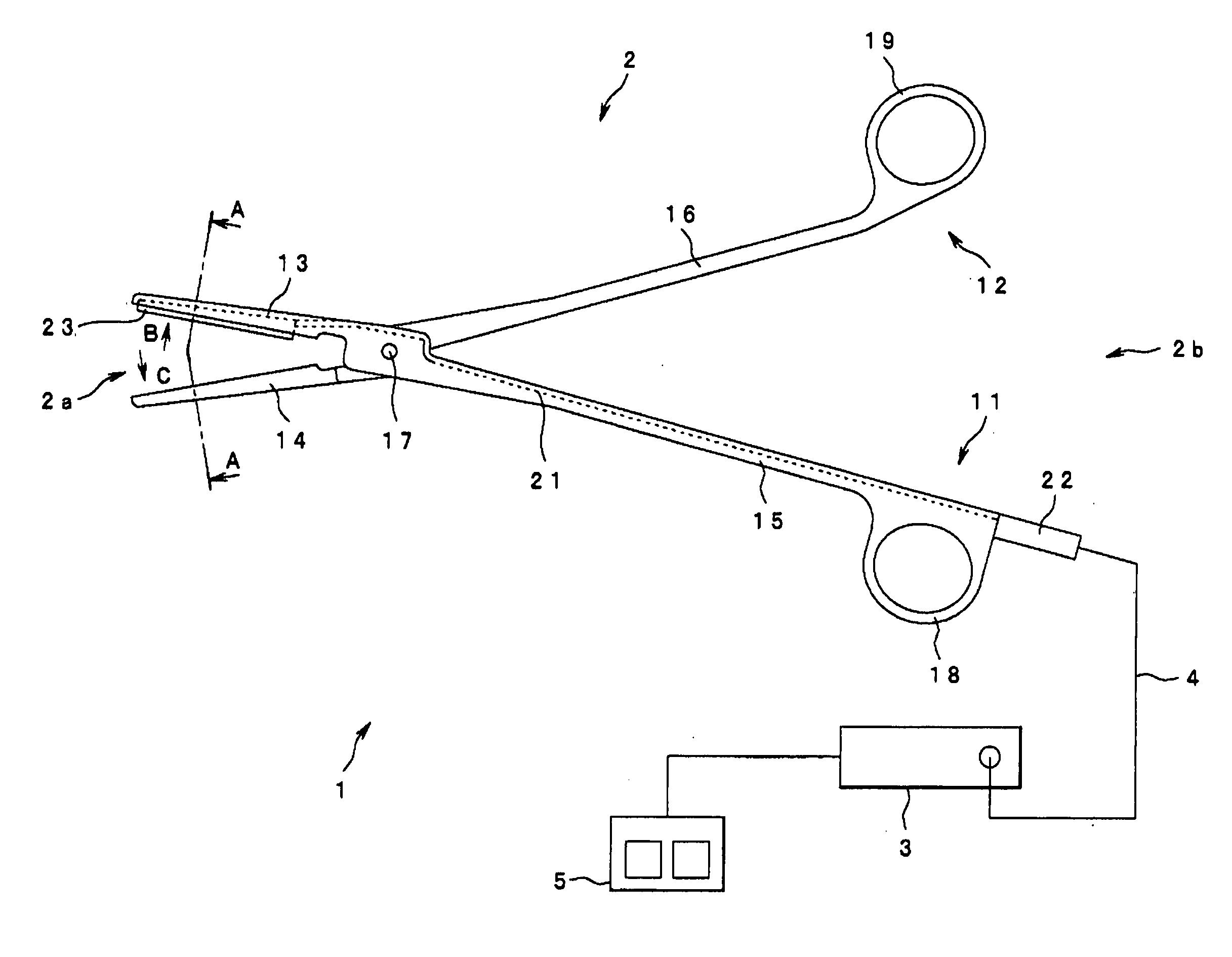
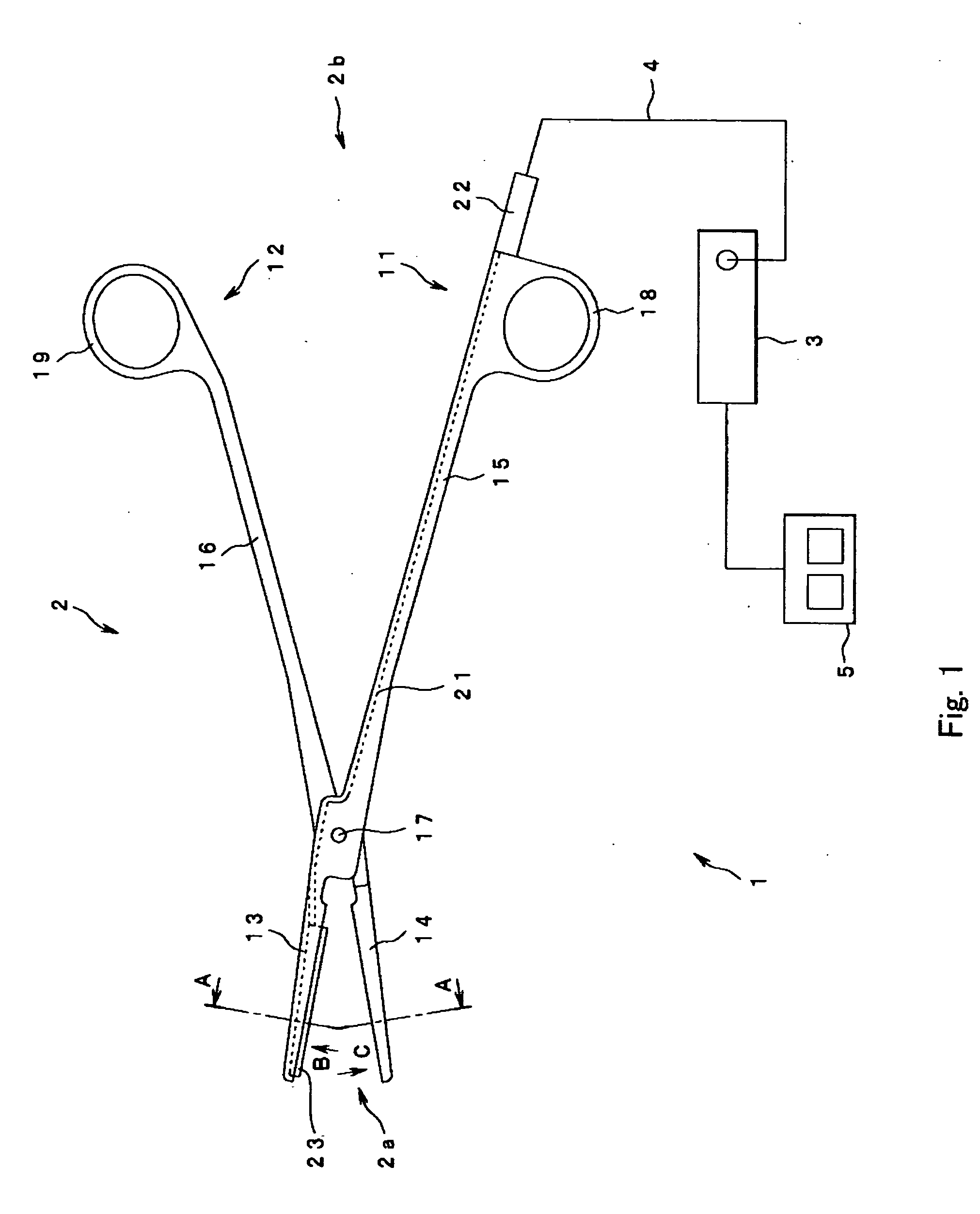
[0061] As shown in FIG. 1, an operative instrument 1 of the first embodiment includes forceps 2 that provide heat to an anatomy which they grip to effect coagulating and incising that anatomy. A power supply unit 3 that can be disconnectably connected to the forceps 2 outputs electric power of a power source (electric energy) to the forceps 2 to drive and control the same.

[0062] The forceps 2 are adapted in such a manner that a connector (not shown) provided at the rear end of a connecting cord 4 extending therefrom can be disconnectably connected to the power supply unit 3.

[0063] A foot switch 5 can be connected to the power supply unit 3. The operator can turn the power source to the forceps 2 ON and OFF by turning the foot switch 5 ON and OFF. A front panel of the power supply unit 3 is provided with a display device for displaying a current value or a voltage value of the power source supplied to the forceps 2 and an operating tab for entering various setting values on a panel ...

second embodiment

[0108]FIG. 17 to FIG. 20 is a graph of output control performed by the control circuit according to the invention. FIG. 17 is a graph of output voltage with respect to time; FIG. 18 is a graph of output current with respect to time; FIG. 19 is a graph of output electric power with respect to time; and FIG. 20 is a graph of electric resistance of the heat-generating body with respect to time.

[0109] Although constant voltage control is performed in the first embodiment, constant current control is performed in the second embodiment. Other structures are the same as the first embodiment and hence will not be described again, and the same structures are represented by the same reference numeral in description.

[0110] In other words, as shown in FIG. 17 to FIG. 20, the operative instrument 1 of the second embodiment is controlled in such a manner that the current I flowing in the heat-generating body 23 is kept constant (constant current control), and output is stopped when the heat-gene...

third embodiment

[0119]FIG. 21 to FIG. 24 are graphs of output control performed by a control circuit according to the invention. FIG. 21 is a graph showing output voltage with respect to time; FIG. 22 is a graph of output current with respect to time; FIG. 23 is a graph of output electric power with respect to time; and FIG. 24 is a graph of electric resistance of the heat-generating body with respect to time.

[0120] While constant voltage control is provided in the first embodiment, the third embodiment is based on constant electric power control. Since other structures are the same as in the first embodiment, description will not be made again and the same structures are represented by the same reference numerals in description.

[0121] In other words, in the operative instrument 1 according to the third embodiment, the electric power P supplied to the heat-generating body 23 is kept constant (constant electric power control), and output is stopped when the heat-generating body 23 reaches the prese...


PUM


Abstract

An operative instrument includes forceps having a treating section for treating an anatomy at an extremity and being provided with a heat-generating body for generating heat to be provided to the anatomy and a power supply unit for supplying electric power to the heat-generating body of the forceps. The operative instrument raises the temperature of the heat-generating body by supplying substantially constant electric power to the heat-generating body. Therefore, coagulation and incision of the anatomy can be performed satisfactorily.

Description

CROSS-REFERENCE TO RELATED APPLICATION [0001] This application is based upon and claims the benefit of priority from the prior Japanese Patent Application No. 2004-071405, filed Mar. 12, 2004, the entire contents of the application are incorporated herein by reference. BACKGROUND OF THE INVENTION [0002] 1. Field of the Invention [0003] The present invention relates to an operative instrument for heating an anatomy and coagulating or incising the same. [0004] 2. Description of the Related Art [0005] A known operative instrument heats an anatomy for coagulating or incising the same. The known operative instruments include, for example, a heat treatment instrument, a high-frequency treatment instrument, and an ultrasonic treatment instrument. [0006] The heat treatment instrument heats an anatomy clamped at the extremities of forceps provided with a heat-generating body, such as a heater, for coagulating or incising the same. The high-frequency treatment instrument clamps an anatomy bet...

Claims


Application Information

Patent Timeline
Patent Type & Authority Applications(United States)
IPC IPC(8): A61B17/12A61B18/04A61B18/08A61B18/10A61B18/12A61B18/14
CPCA61B18/085
Inventor KIMURA, KENICHIIIDA, KOJI
Owner OLYMPUS CORP
Why Eureka
Try Eureka