
Relay terminal, base station, charging server, communication system, charging method, program computer data signal, and storage medium

a technology for relay terminals and base stations, applied in data switching networks, frequency-division multiplexes, instruments, etc., can solve problems such as difficulty in expanding service areas, reducing the communication speed and unaware discharge of batteries of radio terminals involved in relaying. to achieve the effect of fair billing

Inactive Publication Date: 2005-10-06
NTT DOCOMO INC
View PDF9 Cites 49 Cited by
  • Summary
  • Abstract
  • Description
  • Claims
  • Application Information

AI Technical Summary

Benefits of technology

[0013] According to the present invention, the contribution to relaying is measured and it can be reflected in billing; therefore, it becomes feasible to give the relay terminal an incentive in the billing server.
[0035] The billing method of the information communication charge according to the present invention can be configured to comprise an identification step of identifying whether a header included in the packets is one associated with relaying; and a step of incrementing a count number of a counter in proportion to the number of packets transmitted and / or received during relaying when the identification step results in identifying an occasion of relaying, and the transmitting step is to transmit a value proportional to the count number as the contribution; in this case, the number of packets can be measured accurately whereby accurate billing can be implemented.

Problems solved by technology

In the application of the ad hoc network to the public communication services, however, there arises the problem that the battery of a radio terminal involved in relaying is discharged unawares because of the relaying to another radio terminal bearing no relation thereto.
The relaying can cause the radio resources to be divided, and possibly result in decreasing the communication speed of the radio terminal involved in the relaying.
Unless the terminal serving for the relaying for others is given some incentive, it is difficult to expand the service areas through the use of the ad hoc network in the public communication systems.
There was no prior art for solving this problem and it was thus difficult to apply the ad hoc network technology to the public communication services.

Method used


Image

  • Relay terminal, base station, charging server, communication system, charging method, program computer data signal, and storage medium
  • Relay terminal, base station, charging server, communication system, charging method, program computer data signal, and storage medium
  • Relay terminal, base station, charging server, communication system, charging method, program computer data signal, and storage medium

Examples


Embodiment Construction

[0056] A relay terminal, a base station, a billing server, a communication system, a billing method, a program, and a storage medium according to an embodiment will be described below. The same elements will be denoted by the same reference symbols, without redundancy of description.

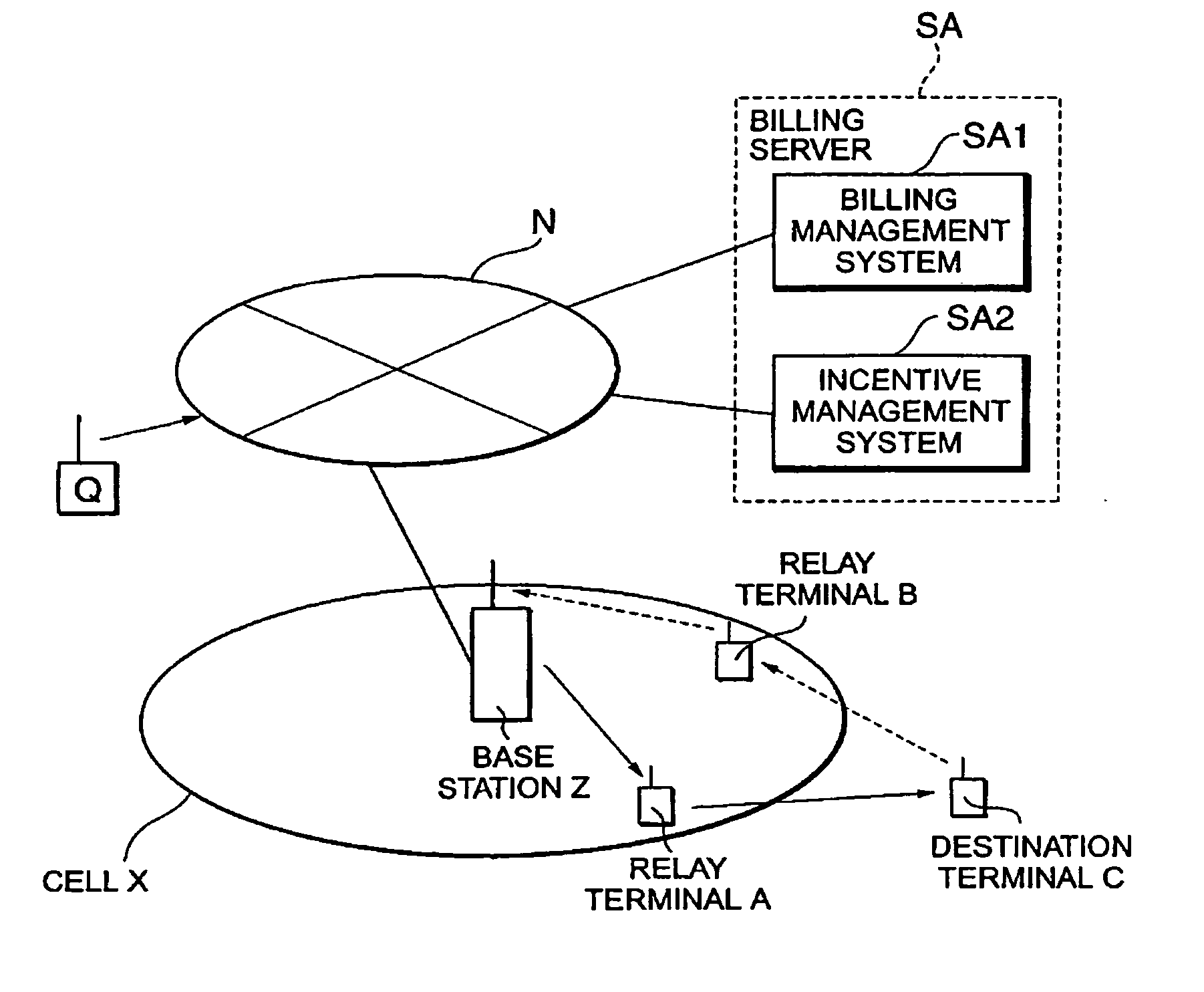
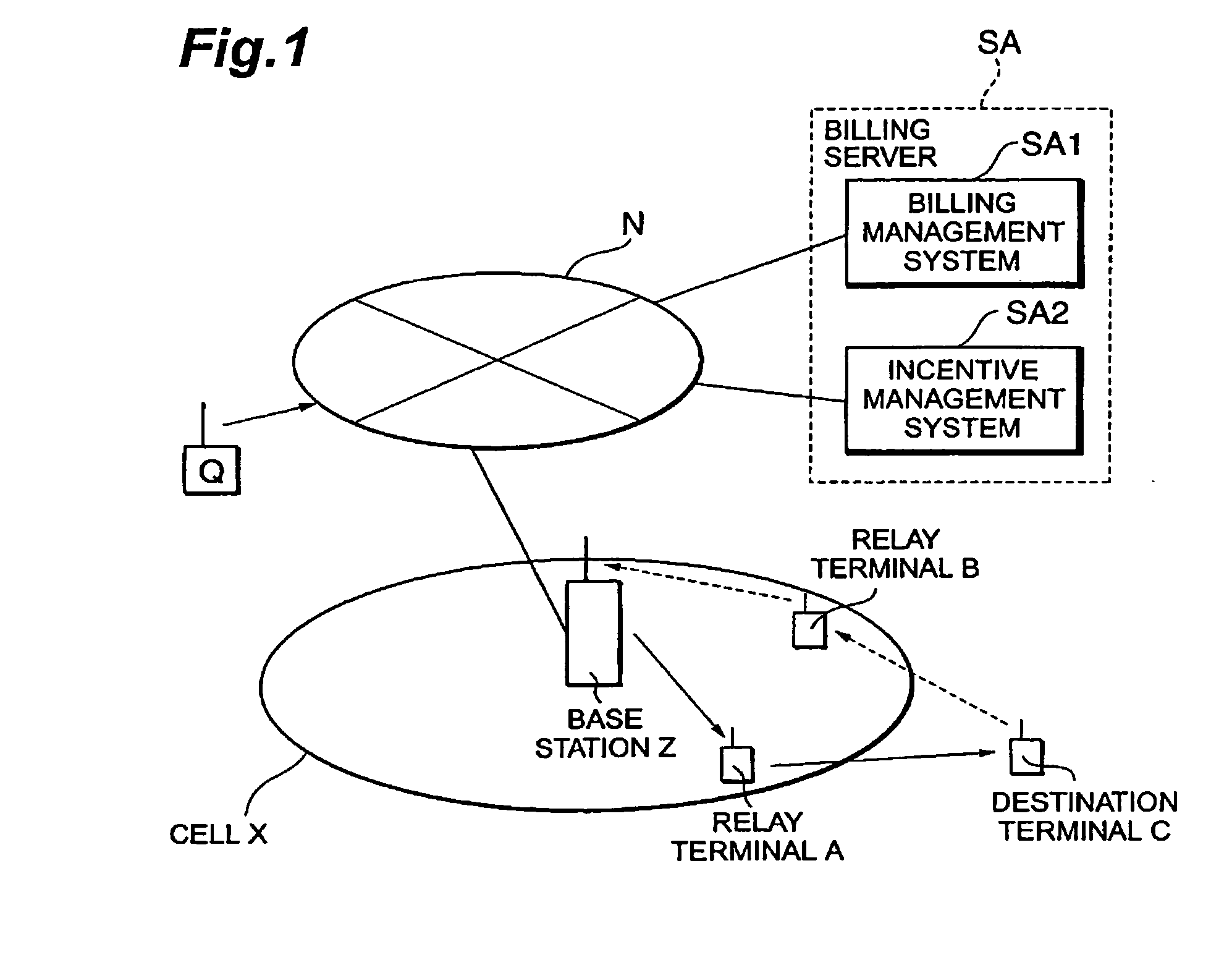
[0057]FIG. 1 is a system configuration diagram according to an embodiment. The base station Z has one cell (service area: zone where radio terminals are communicable with the base station Z) X. Let us assume herein that in the cell X there exist terminal A and terminal B and outside the cell X there exists terminal C. The base station Z is connected to a network N and a billing server SA is connected to the network N. These devices are communicable with each other through the network N.

[0058] First, normal communication will be described. A variety of conceivable structures are available for the network N, but the network N herein is assumed to be a PDC packet communication network permitting billing b...


PUM


Abstract

In a relay terminal A for relaying packet communication between a destination terminal C located outside a service area of a base station Z, and the base station Z, a contribution to relaying is measured and the measurement result is transmitted to a billing server SA configured to store an information communication charge of the relay terminal A, whereby it becomes feasible to give the relay terminal an incentive.

Description

TECHNICAL FIELD [0001] The present invention relates to a relay terminal, a base station, a billing server, a communication system, a billing method, a program, a computer data signal, and a storage medium capable of establishing an optional ad hoc network with a radio terminal (relay terminal) located in a service area in order to secure communication with a radio terminal (destination terminal), particularly, with a destination terminal located outside the service area and making an information communication charge reflect a contribution to relaying, particularly, by the relay terminal on the occasion of determining the information communication charge during communication with the destination terminal. BACKGROUND ART [0002] An ad hoc network in a radio system is normally a network consisting of only radio terminals without intervention of a base station and, for communication with a radio terminal existing in a zone outside a reach of radio waves, i.e., in an uncommunicable zone,...

Claims


Application Information

Patent Timeline
Patent Type & Authority Applications(United States)
IPC IPC(8): H04L12/14H04L12/70H04L12/701H04M15/00H04W4/24H04W16/26H04W40/34H04W88/04
CPCG06Q20/102H04W4/24H04M15/00H04M15/31H04M15/43H04M15/50H04M15/57H04M15/80H04M15/82H04M15/8207H04M15/8214H04M15/825H04M2215/0152H04M2215/2006H04M2215/208H04M2215/22H04M2215/32H04M2215/52H04M2215/78H04M2215/7806H04M2215/7813H04M2215/782H04M2215/7853H04M2215/96H04W88/04H04L12/14
Inventor SATO, HIJINYAMAO, YASUSHI
Owner NTT DOCOMO INC
Learn More