Communication device and communication method

a communication device and communication method technology, applied in the field of communication devices and communication methods, can solve the problems of loss of transmission opportunity of other terminals that set a backoff time and perform backoff, unfair situation may occur among terminals, and many points will interfere with the operation of csma/ca defined by ieee 802.11

Pending Publication Date: 2022-05-26
SONY CORP
View PDF0 Cites 0 Cited by
  • Summary
  • Abstract
  • Description
  • Claims
  • Application Information

AI Technical Summary

Benefits of technology

[0021]According to the technology disclosed in the present specification, it is possible to provide a communication device and a communication method for determining a backoff time during multiband transmission while achieving fairness with peripheral terminals.
[0022]Note that the effects described in the present specification are merely examples, and the effects brought by the technology disclosed in the pre

Problems solved by technology

However, if backoff is always performed in other bands in synchronization with a specific band, there is a concern that many points will interfere with the operation of CSMA/CA defined by IEEE 802.11.
Hence, the band can acquire a transmission opportunity more easily than other terminals that do not perform multiband transmission, and th

Method used


Image

  • Communication device and communication method
  • Communication device and communication method
  • Communication device and communication method

Examples


example 1

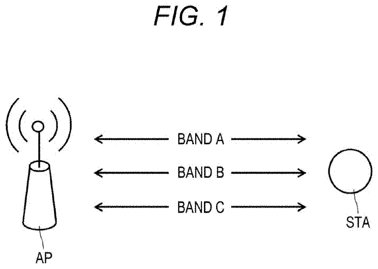
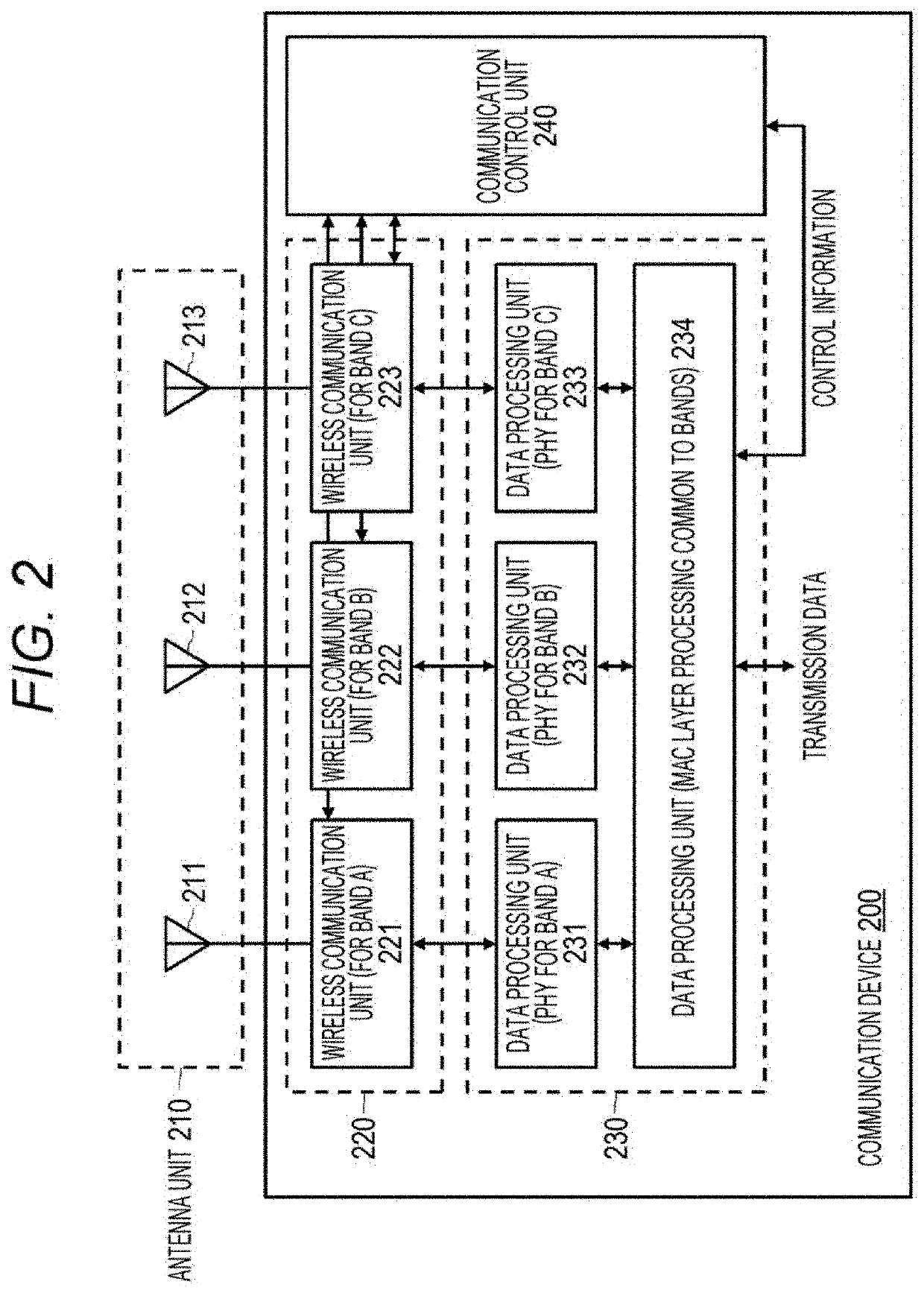
[0075]FIG. 5 illustrates an example of a communication sequence performed between the AP and the STA as a first example. Note that in a communication system including an AP and an STA, it is assumed that three bands A to C are available as illustrated in FIG. 1. Additionally, assume that each of the AP and the STA is equipped with the device configuration illustrated in FIG. 2 and is capable of multiband communication using two or more of the bands A to C.

[0076]In the communication sequence illustrated in FIG. 5, four phases of capability exchange (Capability Exchange), association (Association), MB backoff setup, and data transmission (Data Tx) are mainly assumed. Note that the order of performing the phases is not limited to the example illustrated in FIG. 5. For example, capability exchange may be performed after association. Additionally, the phases are not necessarily separated. For example, capability exchange and association may be performed simultaneously.

[0077]In the associ...

example 2

[0149]In the first example, a reference band is determined from among multiple available bands, and the MB backoff time set in the reference band is compared with the normal backoff time of the other bands. Thus, backoff is set so as to eliminate the unfairness between the STA and the peripheral terminals, and multiband data transmission is performed. However, the STA cannot always set an optimal reference band.

[0150]In other words, the STA sets the reference band on the basis of the MB backoff setup frame received from the AP, but the AP does not always grasp the optimum reference band.

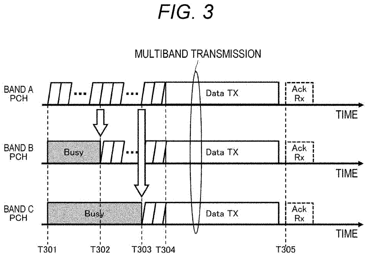
[0151]FIG. 14 illustrates an example of a communication sequence for performing multiband transmission assumed in the first example. FIG. 14 illustrates an operation example for each of the band A, band B, and band C in a case where the STA performs multiband transmission and retransmission using the primary channel (PCH) of each band Note, however, that the STA is assumed to have the device configur...


PUM


Abstract

A communication device that determines a backoff time of multiband transmission is provided.
A communication device includes: a communication unit that transmits and receives wireless signals in a plurality of bands; and a control unit that controls an operation in the communication unit. The control unit sets, for each band, a first random standby time for performing transmission in each of the plurality of bands, sets a second random standby time for performing simultaneous transmission of data in two or more of the plurality of bands, and controls countdown of the second random standby time or the first random standby time of each band on the basis of a comparison between the first random standby time of each band and the second random standby time.

Description

TECHNICAL FIELD[0001]The technology disclosed in the present specification relates to a communication device and a communication method for transmitting and receiving wireless signals.BACKGROUND ART[0002]In recent years, in order to cope with an increase in required data traffic, there has been a need to increase data capacity and improve the peak throughput in a wireless local area network (LAN). For this reason, multiband transmission in which communication is performed by simultaneously using multiple communication bands (hereinafter also referred to as “bands”) has been attracting attention (see Patent Document 1, for example), and has been expected to be standardized as a next-generation standard of IEEE 802.11.[0003]According to the current carrier sense multiple access with collision avoidance (CSMA / CA), backoff in which countdown of a random standby time (hereinafter also referred to as “backoff time”) is performed in a primary channel (hereinafter also denoted as “PCH”) of ...

Claims


Application Information

Patent Timeline
IPC IPC(8): H04W74/08
CPCH04W74/0816H04W84/12H04W74/0841
Inventor AIO, KOSUKETANAKA, YUSUKESUGAYA, SHIGERU
Owner SONY CORP
Why Eureka
Try Eureka