System and method providing mapped network object performance information

a network object and performance information technology, applied in the field of communication networks, can solve the problems of difficult to locate network objects with performance problems and failures, difficult to accurately estimate the impact of moving various network devices from one location to another, and the complexity of communication networks is increasing

Active Publication Date: 2005-10-06
EMC IP HLDG CO LLC
View PDF47 Cites 60 Cited by
  • Summary
  • Abstract
  • Description
  • Claims
  • Application Information

AI Technical Summary

Benefits of technology

[0009] In another aspect of the invention, the system further provides a graphical display of performance data for one or more of the mapped network objects. The graphical display can include a threshold for readily determining times at which the threshold is exceeded.

Problems solved by technology

As is known in the art, communication networks are becoming increasingly complex.
Locating networks objects having performance problems and failures may be relatively difficult.
In addition, a network problem may not be a component failure but rather a device that is overloaded periodically or from time to time.
Further, an administrator responsible for allocating network resources may find it quite difficult to correctly estimate the impact of moving various network devices from one location to another.
This requires a user to mentally combine the information in the two views, which may be quite difficult for complex networks with a variety of components, to determine the probable location of a problem.
In addition, known systems may not collect object performance information with sufficient granularity to help a user identify intermittent bottlenecks or problems.

Method used


Image

  • System and method providing mapped network object performance information
  • System and method providing mapped network object performance information
  • System and method providing mapped network object performance information

Examples


Embodiment Construction

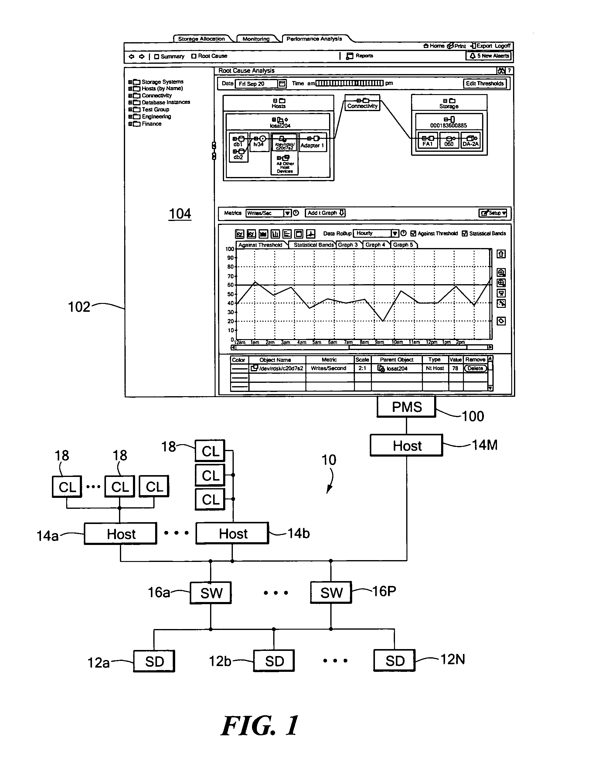
[0035]FIG. 1 shows an exemplary network object performance monitoring system 100 coupled to an illustrative storage area (SAN) network 10 in accordance with the present invention. In general, the system 100 includes a display 102 providing a graphical user interface 104 for enabling a user to interactively identify network failures, trigger firings, alerts, and performance issues.

[0036] The performance monitoring system 100 can be coupled to the network 10 for monitoring the performance of the various network objects. The illustrated network 10 includes storage devices 12a-12N coupled to a series of host devices 14a-14M via connectivity devices 16a-16P, such as SAN switches. Clients 18, including the performance monitoring system 100, can be coupled to the various host devices 14.

[0037] It is understood that the network configuration, devices, etc., can be readily varied without departing from the present invention. In addition, additional types of network objects not specifically...


PUM


Abstract

A method and apparatus displays time-based alert information for network objects in a summary view. In another embodiment, a method and apparatus displays time-based alert information in a topographical map display. In a further embodiment, a method and apparatus displays time-based alert information in a graphical display for one or more network objects. In another embodiment, a method and apparatus displays time-based alert information in a graphical display for one or more network objects along with statistical bands. In a further embodiment, a method and apparatus displays time-based alert information in a graphical display with thresholds set with historical data.

Description

CROSS REFERENCE TO RELATED APPLICATIONS [0001] Not Applicable. STATEMENT REGARDING FEDERALLY SPONSORED RESEARCH [0002] Not Applicable. FIELD OF THE INVENTION [0003] The present invention relates generally to communication networks and, more particularly, to systems and methods for monitoring network object performance. BACKGROUND OF THE INVENTION [0004] As is known in the art, communication networks are becoming increasingly complex. Locating networks objects having performance problems and failures may be relatively difficult. A system administrator may need to obtain an intimate working knowledge of the network topology, components, and operating parameters to even make a guess at a potential problem in the network. In addition, a network problem may not be a component failure but rather a device that is overloaded periodically or from time to time. Further, an administrator responsible for allocating network resources may find it quite difficult to correctly estimate the impact o...

Claims


Application Information

Patent Timeline
Patent Type & Authority Applications(United States)
IPC IPC(8): G06F15/173H04L12/24H04L12/26
CPCH04L41/0631H04L41/0681H04L41/142H04L41/22H04L43/00H04L43/045H04L43/067H04L43/0811H04L43/0817H04L43/0852H04L43/16
Inventor SAPIRO, LEE W.ZAHAVI, WILLIAM Z.ARDEN, JENNIFER
Owner EMC IP HLDG CO LLC
Why Eureka
Try Eureka