Image displaying method, image displaying program, and display

Inactive Publication Date: 2005-10-06
CANON KK
View PDF10 Cites 30 Cited by
  • Summary
  • Abstract
  • Description
  • Claims
  • Application Information

AI Technical Summary

Benefits of technology

[0011] It is an object of the invention to improve the opera

Problems solved by technology

However, according to those proposed methods, the layouts have been predetermined and the images cannot be freely arranged.
There is, consequently, a case where those methods are not proper with the important areas hidden or the like.
In the case of a television receiver or an AV apparatus which is used in a living room at home, ho

Method used


Image

  • Image displaying method, image displaying program, and display
  • Image displaying method, image displaying program, and display
  • Image displaying method, image displaying program, and display

Examples


Example

Embodiment 1

[0027] An image displaying method according to the embodiment 1 of the invention will be described with reference to FIGS. 1 to 5A through 5G.

[0028] In the embodiment, the case of using an image displaying system constructed by a digital camera and a digital television having a function of visualizing image data photographed by the digital camera and viewing an obtained visual image will now be described as an example.

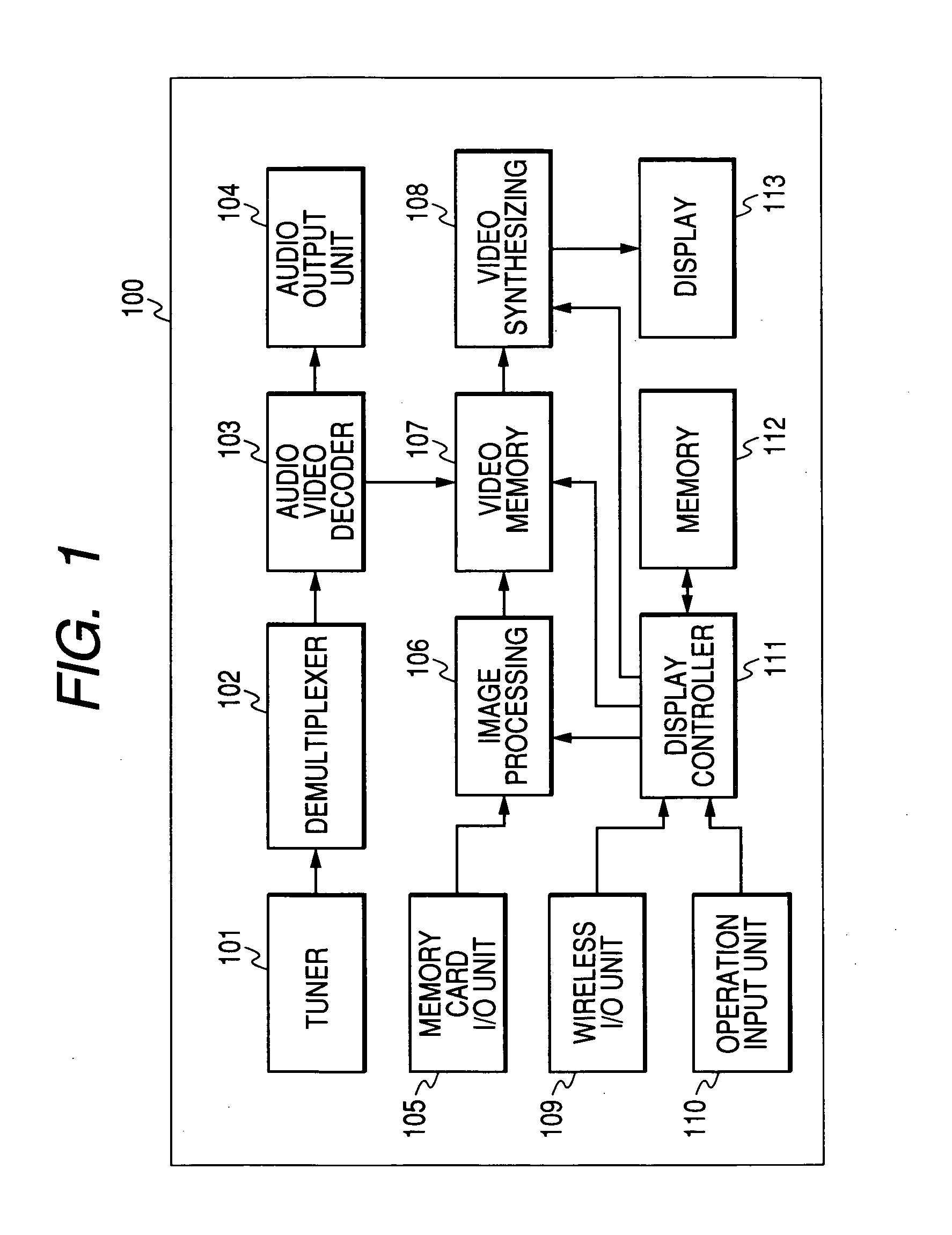
[0029]FIG. 1 is a block constructional diagram of the digital television which is used in the image displaying method according to the embodiment 1 of the invention. In the diagram, reference numeral 101 denotes a tuner. A broadcast signal from a receiving antenna (not shown) of a digital broadcast and a broadcast signal of a CATV are inputted to the tuner 101. The tuner 101 selects a predetermined transmission channel from the reception signal on the basis of control of a display controller 111, which will be explained hereinafter, executes demodulation...

Example

Embodiment 2

[0058] An image displaying method according to the embodiment 2 of the invention will now be described with reference to FIGS. 6 to 11A through 11G.

[0059] The embodiment will be explained with respect to an example in the case of using a system in which the digital camera and the digital video camera are connected, the digital televisions each having a function for visualizing the photographed image of the digital camera and allowing the user to view it are connected by a network, and the viewing of the photographed image of the digital camera is shared.

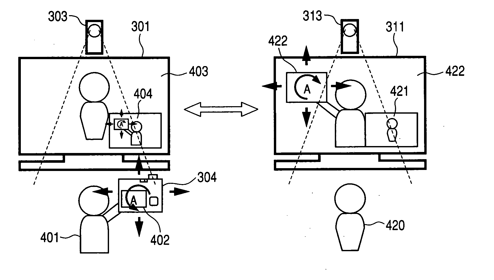
[0060]FIG. 6 is a constructional diagram of the whole system which is used in the image displaying method according to the embodiment 2 of the invention. In FIG. 6, reference numeral 301 denotes a digital television (1) for receiving a broadcast wave through an antenna 302 and viewing a television program. The digital television (1) 301 has a function for receiving photographed image data from a digital camera (1) 304 ...


PUM


Abstract

An image displaying method of displaying an image selected from images stored in an image storing apparatus onto a display has the step of displaying the image selected from the images stored in the image storing apparatus into a partial area on the display based on a relative positional relation between the image storing apparatus and the display.

Description

BACKGROUND OF THE INVENTION [0001] 1. Field of the Invention [0002] The invention relates to an image displaying method of arranging a plurality of images on a display, a program for executing the image displaying method, and a display which is used for displaying the images. [0003] 2. Related Background Art [0004] Various methods of arranging a plurality of images photographed by a digital camera in a desired layout have been proposed. For example, a method whereby a layout according to the number of images to be displayed is selected from prepared layouts and image data, character data, and figure data are inserted and arranged has been disclosed in Japanese Patent Application Laid-Open No. H07-184032. Another method whereby a sheet describing a pattern which designates a layout and a sheet to designate image data to be arranged are read, thereby designating the layout, has also been disclosed in Japanese Patent Application Laid-Open No. H10-051576. However, according to those pro...

Claims


Application Information

Patent Timeline
IPC IPC(8): G06F3/00G06F3/033G06F3/0346G06F3/038G06F3/048G06F3/0487G09G5/00G09G5/38H04N5/225H04N5/445H04N21/4223H04N21/431H04N21/4788H04N21/81
CPCG06F3/04845H04N5/44591H04N7/142H04N7/147H04N21/4223H04N21/4316H04N21/4788H04N21/8153H04N21/47
Inventor YAMAMOTO, TAKASHIOHNO, TOMOYUKI
Owner CANON KK
Why Eureka
Try Eureka