

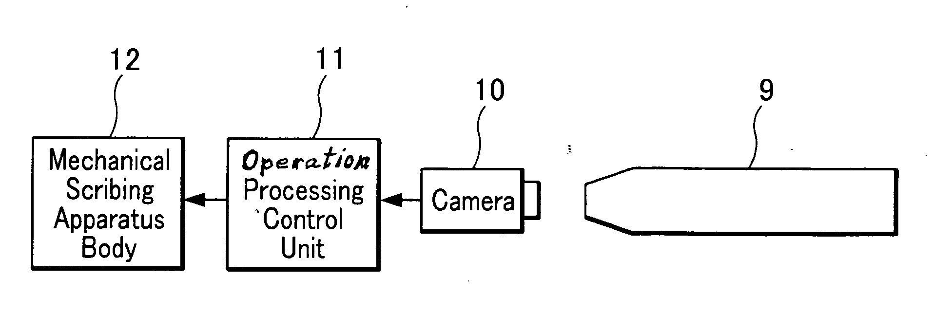
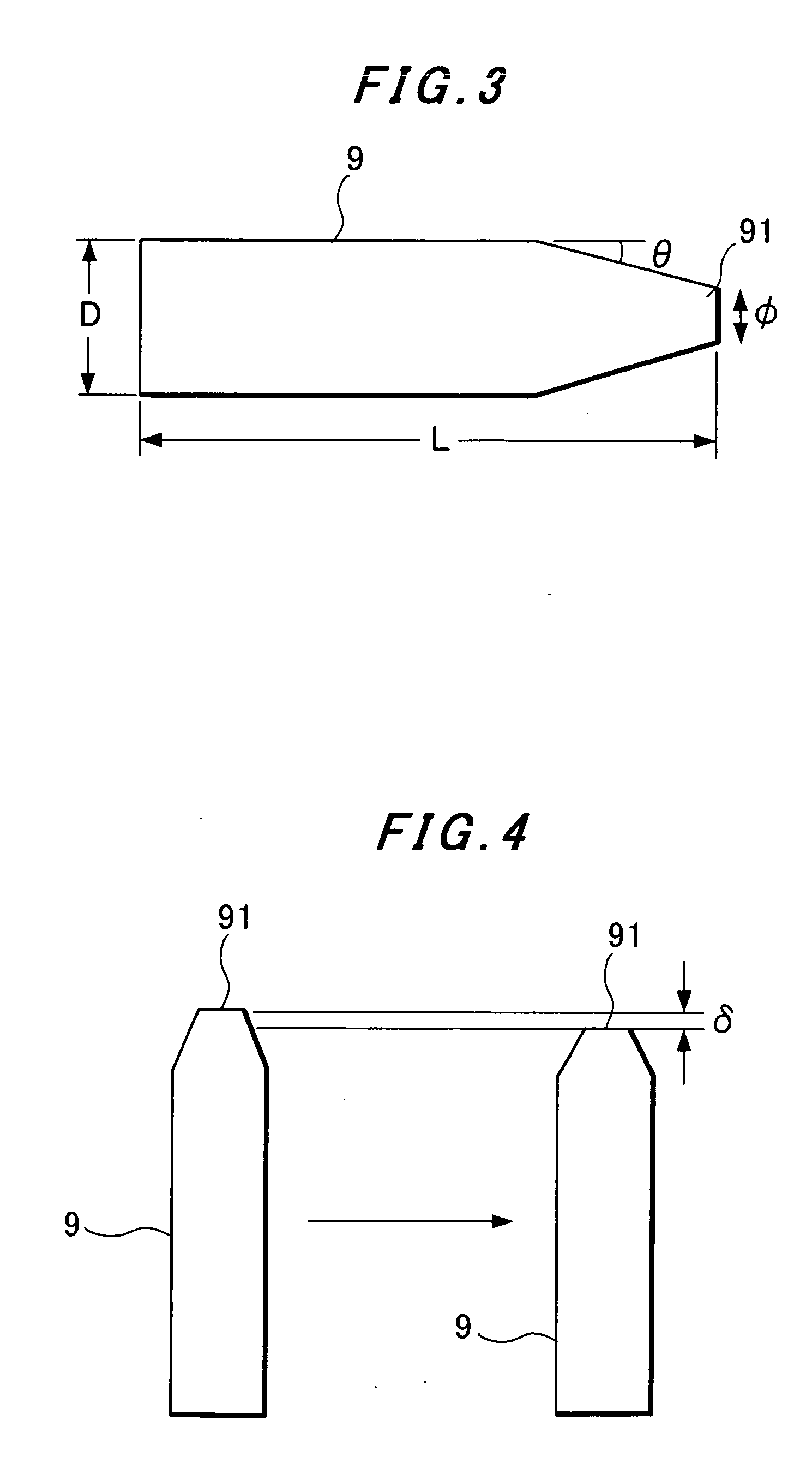
Mechanical scribing apparatus with controlling force of a scribing cutter
a technology of mechanical scribing and scribing cutter, which is applied in the direction of writing aids, glass making apparatus, manufacturing tools, etc., can solve the problems of deterioration of performance characteristics of respective cells and the deterioration of cell characteristics by heat, so as to prevent excessive cutting of solar cells
- Summary
- Abstract
- Description
- Claims
- Application Information
AI Technical Summary
Benefits of technology
Problems solved by technology
Method used
Image

Examples
Embodiment Construction
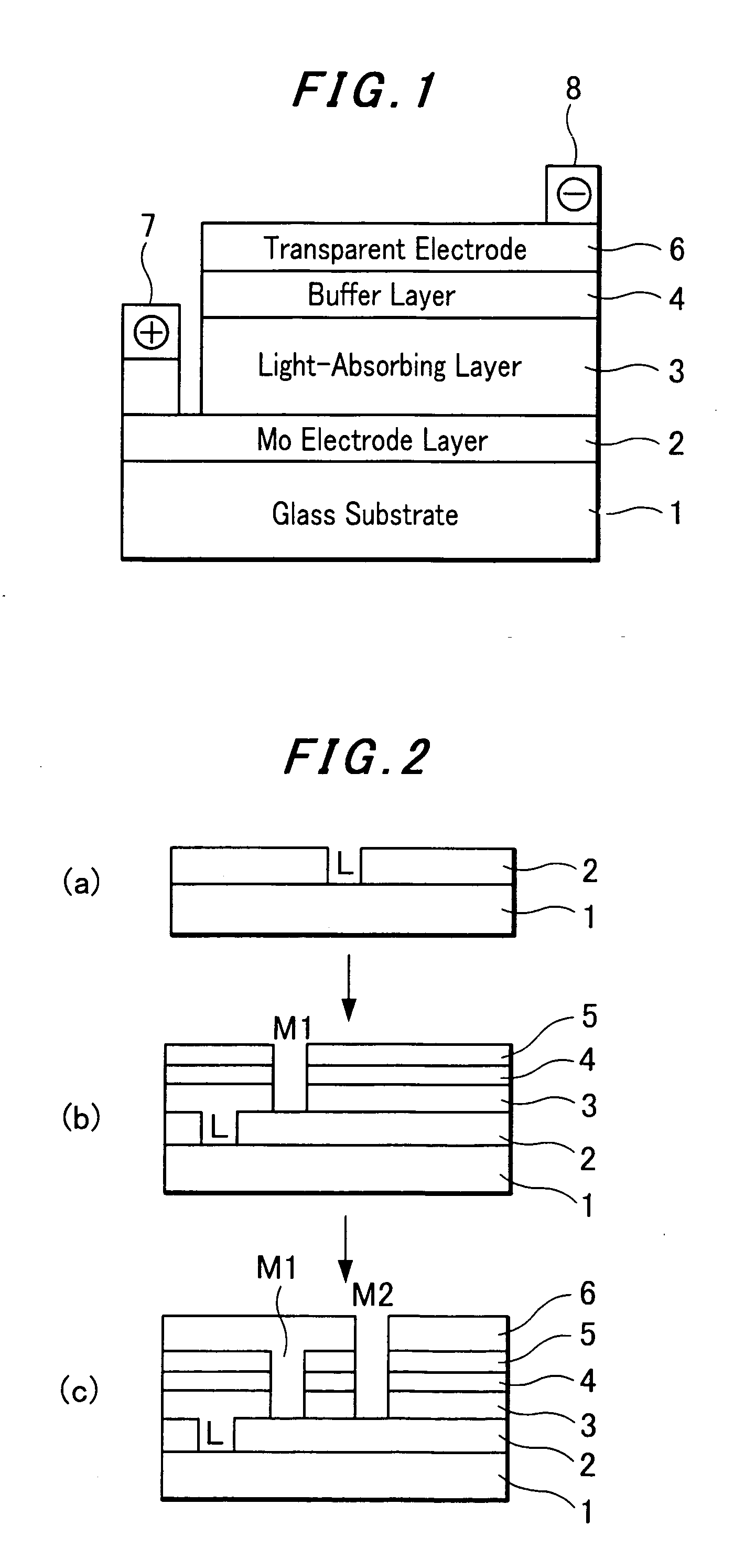
[0021] In FIG. 2, there is shown a basic process of mechanical scribing in the production of compound thin-film solar cells formed on a single substrate.
[0022] As shown in FIG. 2(a), the first process is to form a lower molybdenum (Mo) electrode layer 2 by sputtering on a SLG (soda lime glass) substrate 1 and then a separating groove L is formed by laser scribing in the Mo-electrode layer formed on the substrate. In this stage, the laser scribing has no significant influence by heat on the performance of the solar cell products. Next, as shown in FIG. 2(b), the second process is to form a compound semiconductor film (CIGS) light absorbing layer 3 on the lower Mo-electrode layer 2, a ZnS buffer layer 4 for providing hetero-junction by a chemical bath deposition (CBD) method and a ZnO insulating layer 5 by a sputtering method on the buffer layer 4 and then form a groove M1 for forming a contact between the upper and lower electrode layers by mechanical scribing of the layers in depth...
PUM
| Property | Measurement | Unit |
|---|---|---|
| Angle | aaaaa | aaaaa |
| Angle | aaaaa | aaaaa |
| Force | aaaaa | aaaaa |
Abstract
Description
Claims
Application Information