Compaction wheel and cleat assembly therefor

a technology of cleats and wheels, applied in the field of compaction wheels, can solve the problems of prior cleat designs suffering from several drawbacks, dirty and highly undesirable work, and needing replacement of cleats

Inactive Publication Date: 2005-10-13
GIBBINS JOHN
View PDF14 Cites 27 Cited by
  • Summary
  • Abstract
  • Description
  • Claims
  • Application Information

AI Technical Summary

Benefits of technology

[0011] According to a first aspect of the present invention there is provided a compaction wheel for landfill compactors, the compaction wheel including a rim and a plurality of cleats secured thereto with a plurality of spring clips, the rim including an exterior surface, an interior surface, and a plurality of cleat-receiving apertures extending therethrough between the exterior and interior surfaces, each of the cleats including a ground-engaging portion, a lug portion extending from the ground-engaging portion, and a clip-receiving aperture extending through the lug portion, each of the cleats being mountable on the rim such that the ground-engaging portions project from the exterior surface of the rim while the lug portions extend through the cleat-receiving apertures of the rim so that the clip-receiving apertures are situated adjacent the interior surface of the rim and lateral movement of the cleats relative to the rim is inhibited, the spring clips being adapted to secure the mounted cleats to the rim by engaging with the clip-receiving apertures and interacting with the rim and cleats such that the ground-engaging portions of the cleats are pulled towards the rim.

Problems solved by technology

With use, the cleats of a compaction wheel become worn and need to be replaced.
Prior cleat designs suffer from several drawbacks in this respect.
This is dirty and highly undesirable work.
Moreover, in two-piece designs, the pins or bolts are situated such that they are often exposed to corrosive materials that can make them difficult to remove.
Additionally, field replacement of the prior art cleats typically requires that service vehicles carry expensive equipment such as air compressors, air hammers, sledge hammers, torches and welding machines.
In use, compaction wheels according to the Kaldenberg et al. patent have been found to perform less than satisfactorily, as the cleats and rods thereof tend to loosen with use so that the cleats are able to move relative to and rub against the outer rim causing the outer rim to wear prematurely.

Method used


Image

  • Compaction wheel and cleat assembly therefor
  • Compaction wheel and cleat assembly therefor
  • Compaction wheel and cleat assembly therefor

Examples


Embodiment Construction

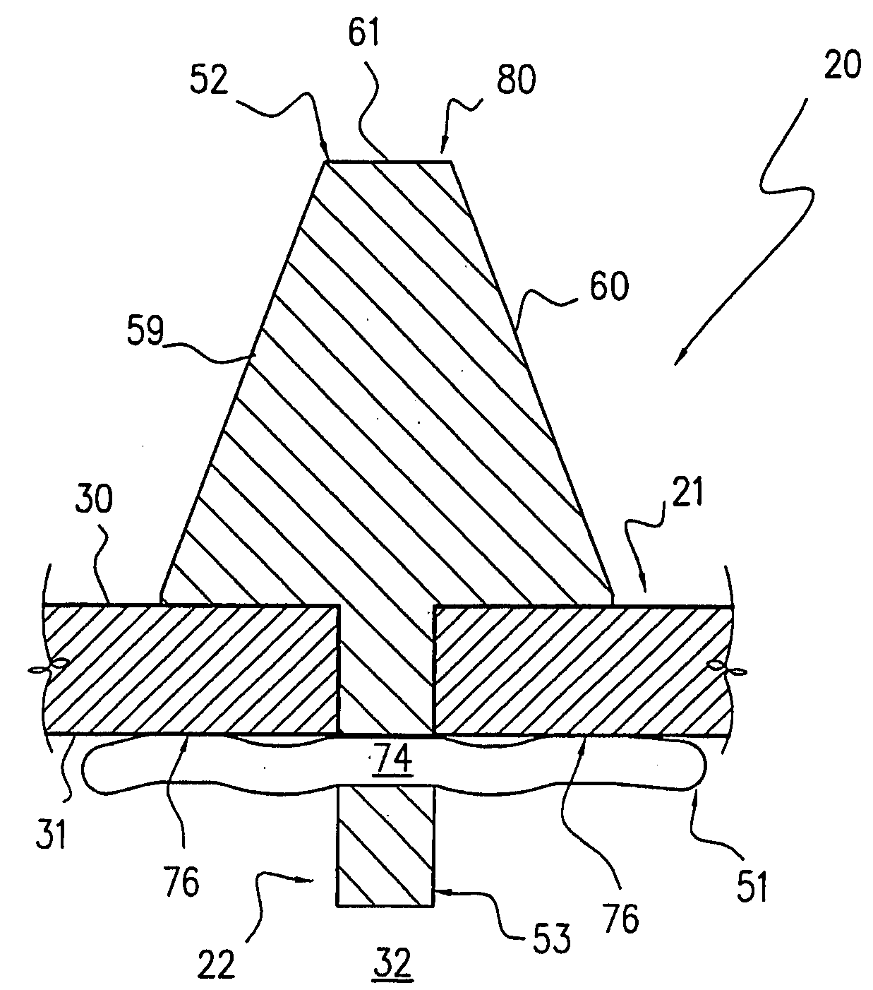
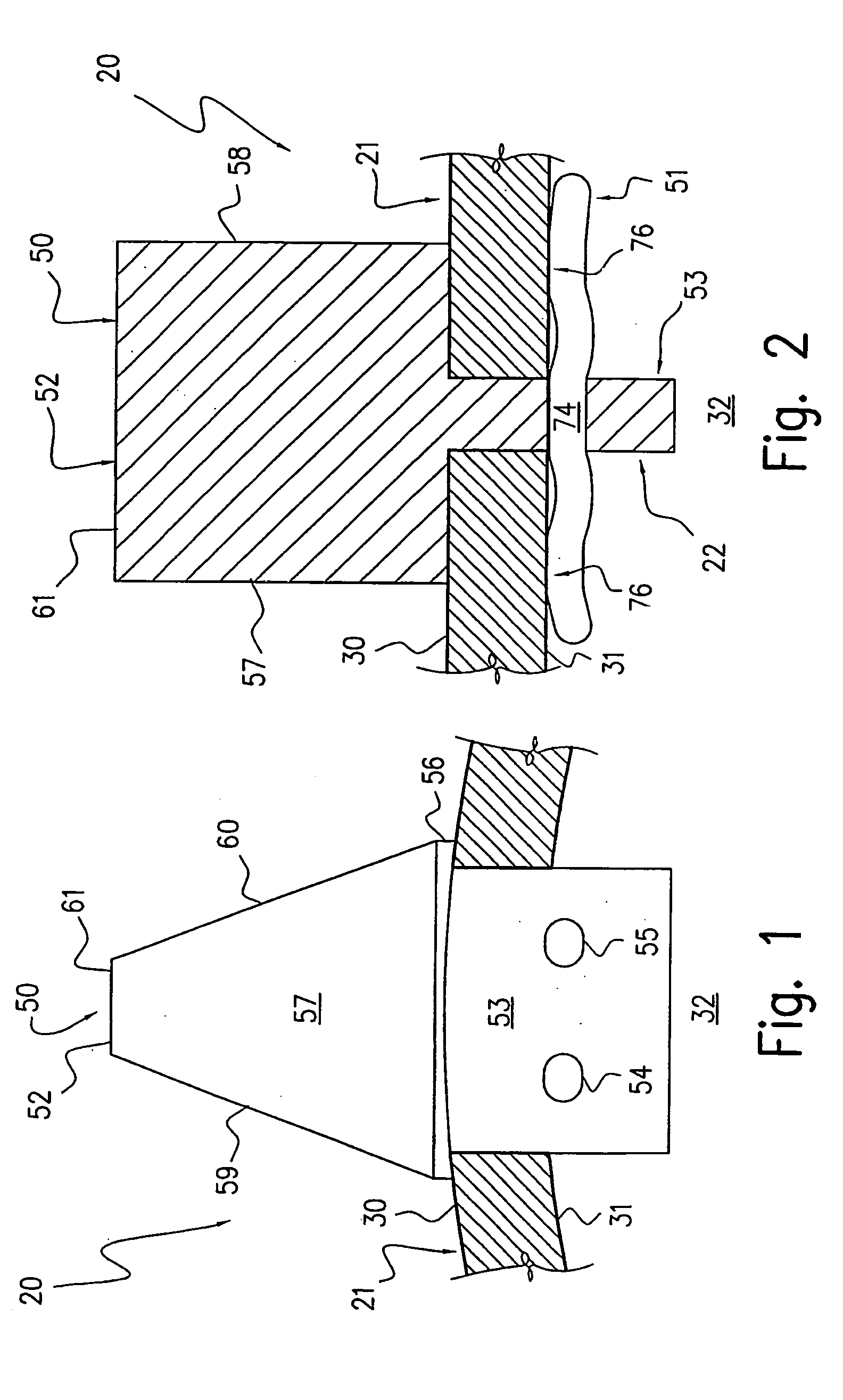
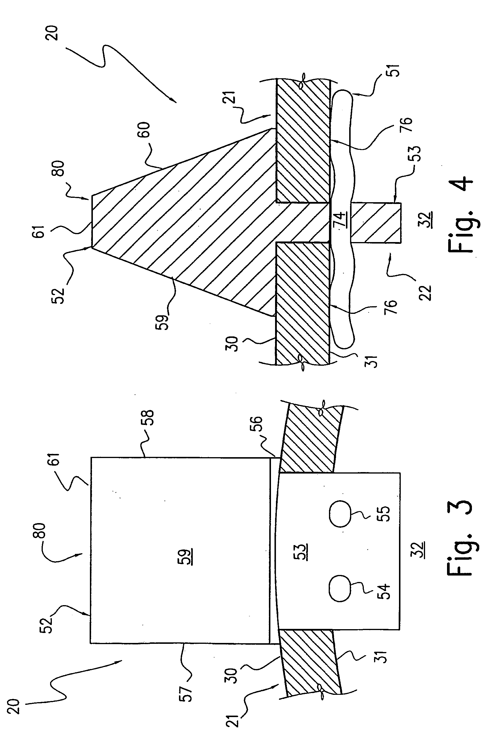
[0036]FIGS. 1 and 2 illustrate a portion of a preferred embodiment of a compaction wheel 20 according to the present invention which may be employed with a landfill compactor. The compaction wheel 20 includes a rim 21 and a plurality of cleat assemblies 22 (note that only one complete cleat assembly 22 is illustrated in FIG. 2) secured thereto.

[0037] Rim 21 is constructed from a suitable material such as steel and is in the form of a hollow cylinder. The rim 21 includes an exterior surface 30, an interior surface 31, and an interior region 32 which is bordered by the interior surface 31.

[0038] Referring to FIGS. 7 and 8, a plurality of rectangular cleat-receiving apertures 33 extend through the rim 21 between the exterior and interior surfaces 30, 31 thereof. The cleat-receiving apertures 33 are arranged into a plurality of bands 34 to 39 (see FIG. 8) which extend around the circumference of the rim 21 such that each band 34 to 39 includes a plurality of circumferentially spaced c...


PUM


Abstract

A compaction wheel (20) for landfill compactors is disclosed. The compaction wheel (20) includes a rim (21) and a plurality of cleats (50, 80) secured thereto with a plurality of spring clips (51). The rim (21) includes an exterior surface (30), an interior surface (31), and a plurality of cleat-receiving apertures (33) extending therethrough between the exterior and interior surfaces (30, 31). Each of the cleats (50, 80) includes a ground-engaging portion (52), a lug portion (53) extending from the ground-engaging portion (52), and a clip-receiving aperture (54, 55) extending through the lug portion (53). Each of the cleats (50, 80) being mountable on the rim (21) such that the ground-engaging portions (52) project from the exterior surface (30) of the rim (21) while the lug portions (53) extend through the cleat-receiving apertures (33) of the rim (21) so that the clip-receiving apertures (54, 55) are situated adjacent the interior surface (31) of the rim (21) and lateral movement of the cleats (50, 80) relative to the rim (21) is inhibited. The spring clips (51) being adapted to secure the mounted cleats (50, 80) to the rim (21) by engaging with the clip-receiving apertures (54, 55) and interacting with the rim and cleats such that the ground-engaging portions (52) of the cleats (50, 80) are pulled towards the rim (21).

Description

FIELD OF THE INVENTION [0001] The present invention generally relates to compaction wheels. In particular, the invention relates to compaction wheels of the type which include a rim and a plurality of cleats secured thereto. [0002] The invention will be described by way of example with reference to compaction wheels for landfill and soil compactors. However, it should be appreciated that this is by way of example only and that the invention may be used in conjunction with other types of compaction wheels. DESCRIPTION OF THE PRIOR ART [0003] Machines such as landfill and soil compactors are usually fitted with compaction wheels instead of crawler tracks or wheel and tyre assemblies. The compaction wheels are specifically designed to crush or compact material such as waste, soil and the like which they pass over. [0004] Compaction wheels of the aforementioned type generally include a cylindrical metal rim having a plurality of metal cleats secured thereto such that the cleats are circ...

Claims


Application Information

Patent Timeline
Patent Type & Authority Applications(United States)
IPC IPC(8): E02D3/026
CPCE02D3/026
Inventor GIBBINS, JOHN
Owner GIBBINS JOHN
Why Eureka
Try Eureka