
Computer-generated hologram fabrication process, and hologram-recorded medium

a technology of computer-generated holograms and holograms, applied in the field of hologram recorded media, can solve the problems of counterfeiting, content decoding of authenticating information recorded as micro-characters, and diffraction grating authentication information, and is vulnerable to copying

Inactive Publication Date: 2005-10-13
DAI NIPPON PRINTING CO LTD
View PDF2 Cites 5 Cited by
  • Summary
  • Abstract
  • Description
  • Claims
  • Application Information

AI Technical Summary

Problems solved by technology

Given recently developed, relatively inexpensive, easy-to-obtain devices capable of recording fine diffraction gratings, there is a possibility that the content of authenticating information recorded as micro-characters may be decoded, and counterfeited by a diffraction grating recorder.
Thus, authenticating information recorded by use of diffraction gratings, because of being recorded directly on a recording surface, is vulnerable to copying.
However, there is still a grave problem with commercialization of computer holograms, that is, excessive computation loads on computers.
Although it is prima facie possible to fabricate a computer hologram equivalent in quality to an optical hologram by implementing long-term computation using a super-fast computer having improved computing power, yet such a fabrication process cannot be utilized for commercial purposes.
Furthermore, the capacity of image data having information on interference fringe patterns fabricated by computation becomes massive, and operational loads on the formation of interference fringes on a physical recording medium using an electron beam lithographic system becomes massive as well.

Method used


Image

  • Computer-generated hologram fabrication process, and hologram-recorded medium
  • Computer-generated hologram fabrication process, and hologram-recorded medium
  • Computer-generated hologram fabrication process, and hologram-recorded medium

Examples


Embodiment Construction

[0085] The present invention is now explained specifically with reference to the preferred embodiments shown in the accompanying drawings.

§1. Fundamental Principles of the Invention

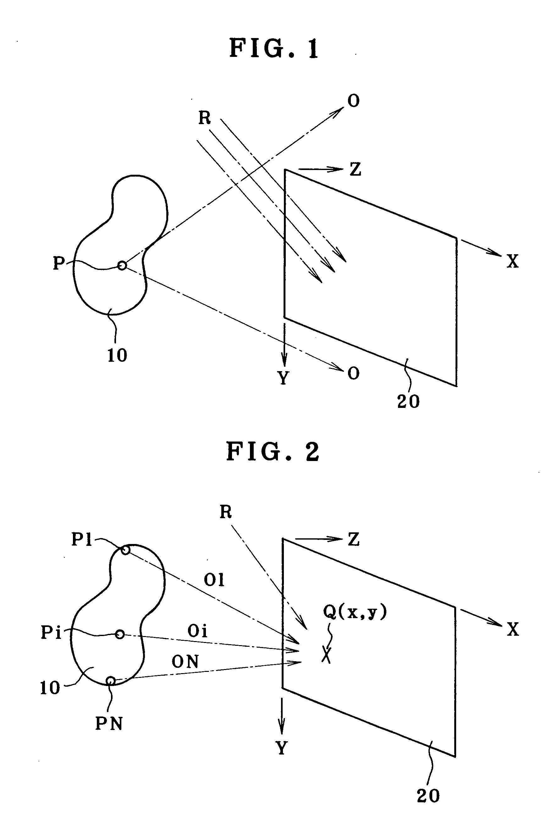
[0086]FIG. 1 is illustrative of the principles of how to fabricate a general hologram, showing how to record an original image 10 in the form of interference fringes on a recording surface 20. For convenience of explanation, assume here that the recording surface 20 is placed on an XY plane on the XYZ three-dimensional coordinate system defined as shown in FIG. 1. When the optical technique is used, an actual object or its real or virtual image is provided as the original image 10. Object light O emanating from an arbitrary point P on the original image 10 propagates toward the whole recording surface 20. On the other hand, the recording surface 20 is irradiated with reference light R, so that interference fringes of object light O and reference light R are recorded on the recording surface 20.

[0087] T...


PUM


Abstract

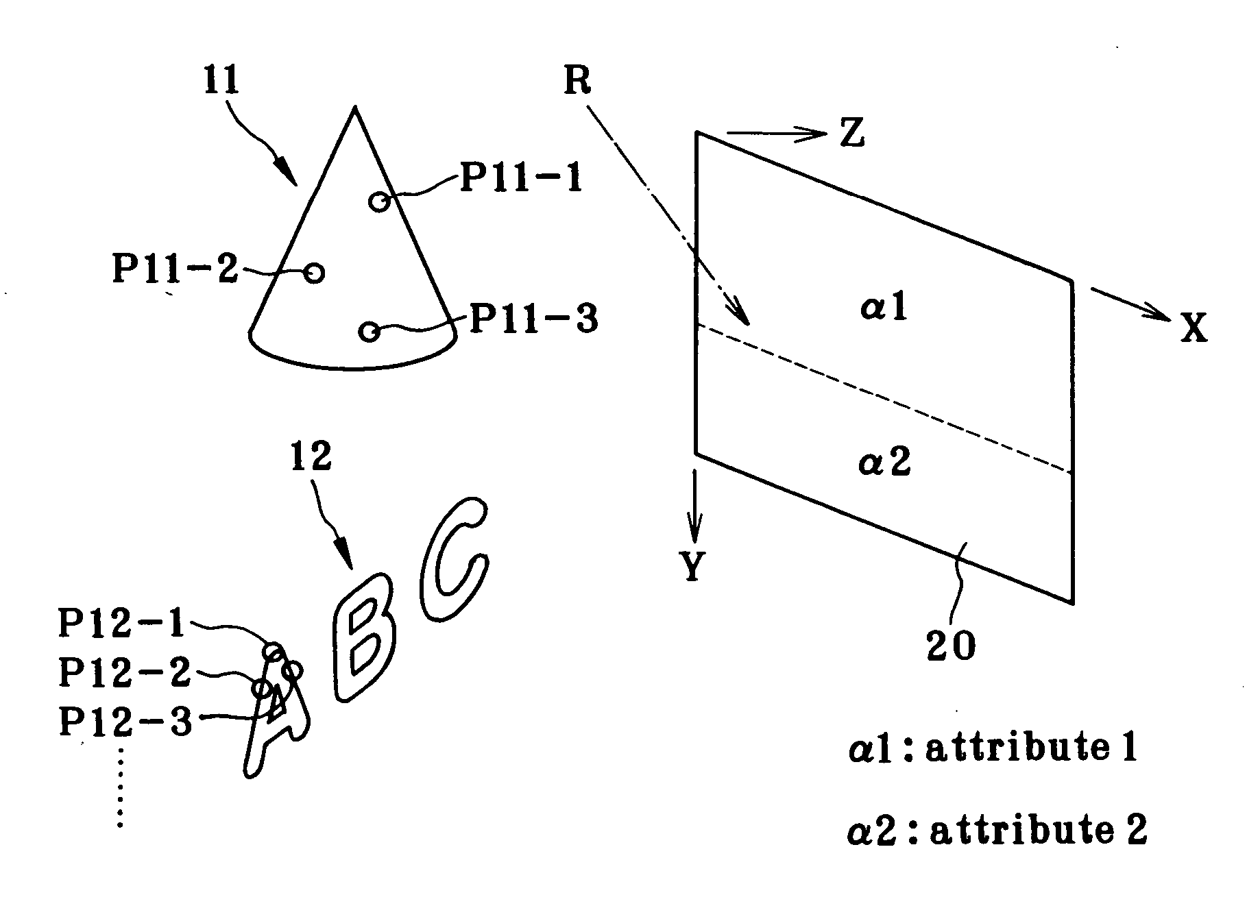
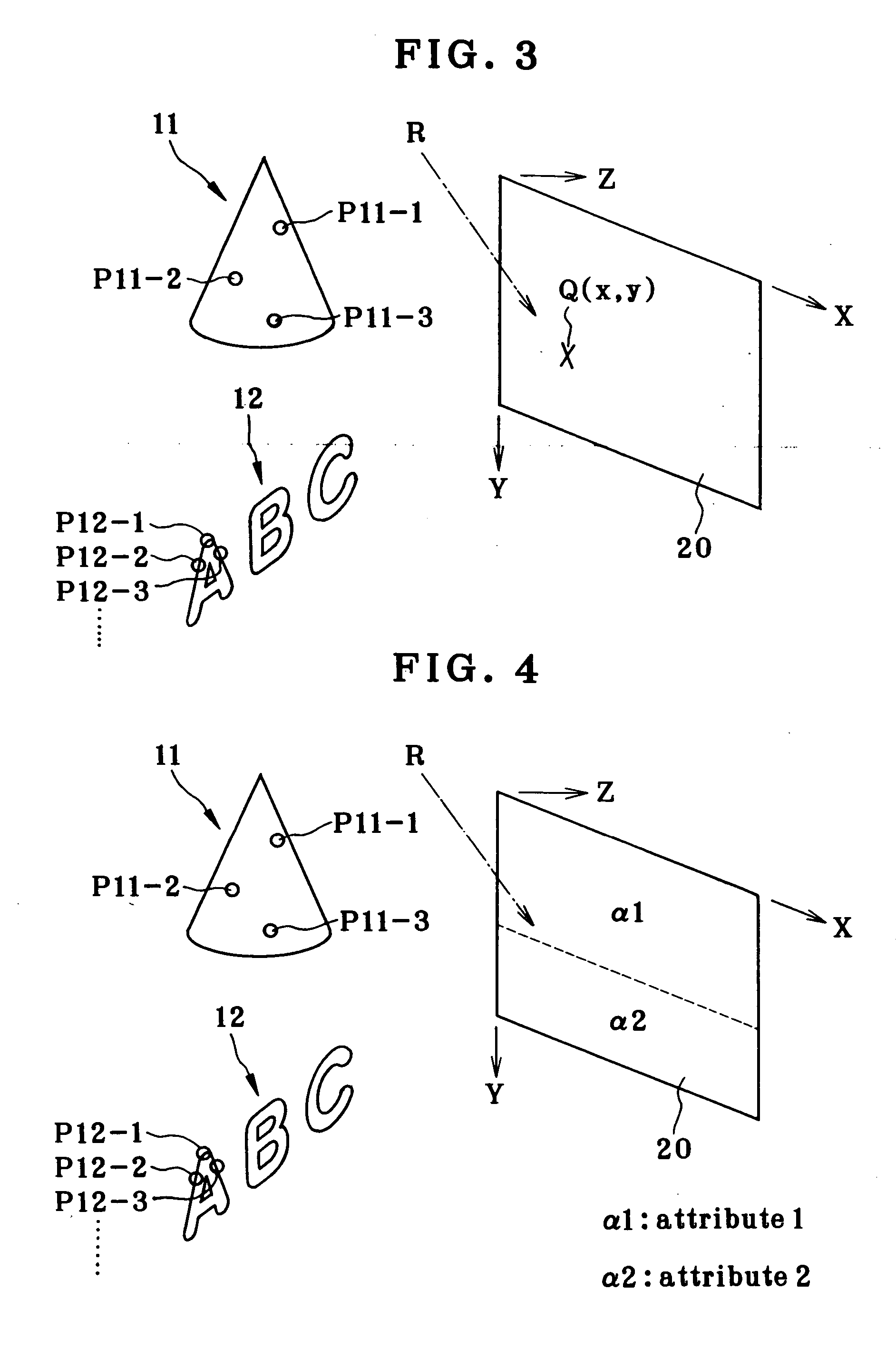
The invention relates to a computer-generated hologram fabrication process that can reduce loads on computation of interference fringes for an original image including micro-characters. A visually perceivable original image 11 and a visually unperceivable original image 12 (micro-characters) are defined, and sample point sources of light P are defined at a low density on the original image 11 and at a high density on the original image 12. Interference fringes of object light coming from the point light sources on the original image 11 and reference light R are found on each computation point within an area α1 on a recording surface 20, and interference fringes of object light coming from point light sources on the original image 12 and reference light R are found on each computation point within an area α2 on the recording surface 20. The light sources that become samples are defined at a given pitch on sectional lines obtained by cutting the original images 11 and 12 by a multiplicity of sections (parallel with an XZ plane) located at a given spacing. The section-to-section spacing for the original image 12 is made narrows than that for the original image 11.

Description

BACKGROUND OF THE INVENTION [0001] The present invention relates to a hologram-recorded medium and a process for the fabrication of the same, and more particularly to a process for the fabrication of a computer-generated hologram in which an optical pattern is formed on a given recording surface by computer-aided computation and a hologram-recorded medium obtained by the same. [0002] In recent years, coherent light has been easily obtainable by use of lasers, and holograms have been widely commercialized as well. Especially for notes and credit cards, the formation of holograms on portions of their media has become popular for anti-counterfeiting purposes. [0003] Today's commercially available holograms are obtained by recording original images on media in form of interference fringes, using optical techniques. That is, an object that forms an original image is first provided. Then, light from this object and reference light are guided through an optical system such as a lens onto a...

Claims


Application Information

Patent Timeline
Patent Type & Authority Applications(United States)
IPC IPC(8): G03H1/26G03H1/08G11C13/04G11C17/00
CPCG03H1/028G03H2210/30G03H1/0891G03H1/30G03H2001/0016G03H2001/0204G03H2001/0858G03H2001/2236G03H2001/2242G03H2001/226G03H2001/2605G03H2001/306G03H2210/32G03H2210/36G03H2210/40G03H2210/452G03H2210/52G03H2210/55G03H2210/56G03H2224/04G03H2240/13G03H2240/56G03H2240/62G03H1/0808
Inventor KITAMURA, MITSURUHAMANO, TOMOHISA
Owner DAI NIPPON PRINTING CO LTD
Learn More