Imaging data server and imaging data transmission system

a technology of imaging data and transmission system, which is applied in the field of imaging data server and imaging data transmission system, can solve the problems of difficulty in and the technique described in patent document 1 also suffers the same problem, so as to achieve the effect of effectively utilizing the network band

Inactive Publication Date: 2005-10-13
FUJITSU LTD
View PDF21 Cites 42 Cited by
  • Summary
  • Abstract
  • Description
  • Claims
  • Application Information

AI Technical Summary

Benefits of technology

[0028] As mentioned above, according to the present invention, the imaging data server can transmit to the monitoring station imaging data pertaining to an object of surveillance—in which the status change is determined to have arisen by the determination section—by means of the priority transmission section, with a higher priority than that employed in the case of imaging data pertaining to an object of surveillance in which no status change is determined to have arisen. Hence, there is an advantage of the ability to form video data to be transmitted to the network in conjunction with a change in the status of the object of surveillance while implementing real-time remote surveillance of the object, as well as the ability to reliably transmit the video data pertaining to the important object of surveillance in which the status change is determined to have arisen while supplying video data conforming to an operating condition and effectively utilizing a band of the network.

Problems solved by technology

Hence, there is a problem of difficulty in effectively utilizing the network band.
Hence, the technique described in Patent Document 1 also suffers the same problem as that encountered by the imaging data transmission system 100.

Method used


Image

  • Imaging data server and imaging data transmission system
  • Imaging data server and imaging data transmission system
  • Imaging data server and imaging data transmission system

Examples


Embodiment Construction

[0045] An embodiment of the present invention will now be described by reference to the drawings.

[0046] [A] Description of the Entire Configuration of an Imaging Data Transmission System According to an Embodiment

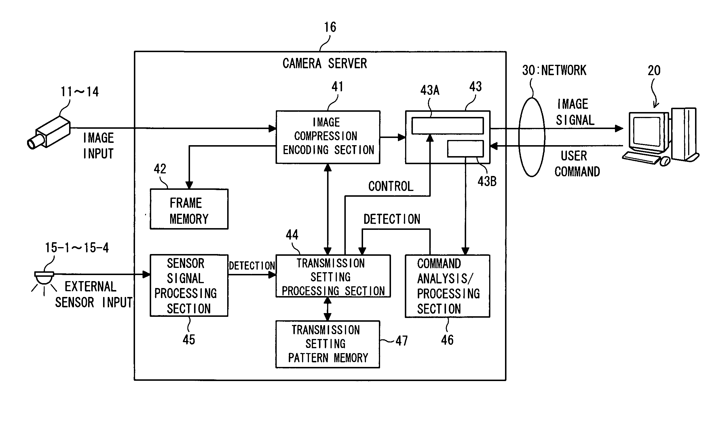
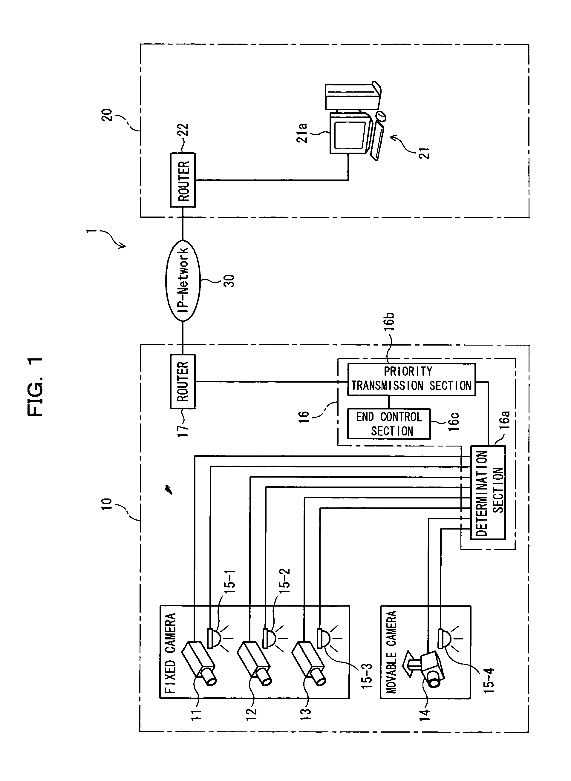
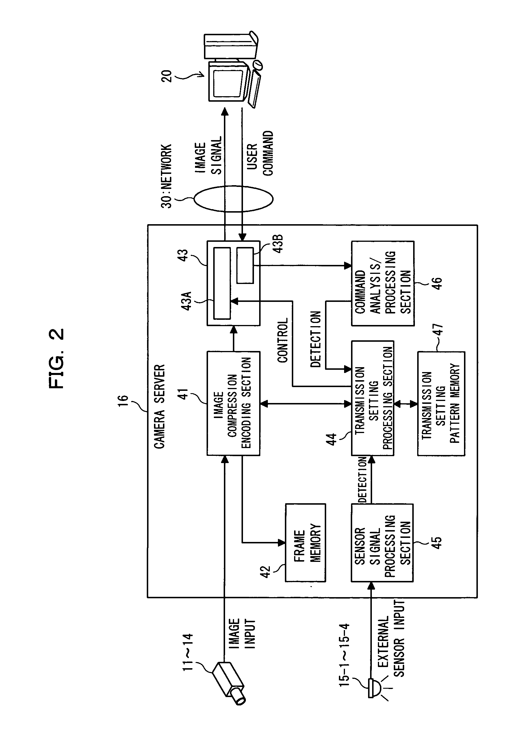
[0047]FIG. 1 is a block diagram showing an imaging data transmission system 1 according to an embodiment of the present invention. The imaging data transmission system 1 shown in FIG. 1 can also be applied to a system intended for preventing occurrence of crime on the streets and in shopping districts, in schools or other important facilities, or on the premises thereof, wherein the imaging data transmission system takes these locations or facilities as objects of surveillance; wherein images of the locations or facilities are captured by a camera; and wherein the thus-captured images are monitored by means of a monitor at a place remote from the object of surveillance.

[0048] As in the case of the conventional imaging data transmission system shown in FIG. 16, the imagin...


PUM


Abstract

The present invention relates to an imaging data server. The imaging data server acquires a plurality of types of imaging data pertaining to a plurality of objects of surveillance and transmits the acquired imaging data to a monitoring station over a network. The imaging data server comprises determination section for determining whether or not a change has arisen in the status of each of the objects of surveillance pertaining to a plurality of types of the imaging data; and a priority transmission section for transmitting, to the monitoring station, imaging data pertaining to an object of surveillance in which the status change is determined to have arisen by the determination section, with a higher priority than that utilized in the case of imaging data pertaining to an object of surveillance in which no status change is determined to have arisen.

Description

BACKGROUND OF THE INVENTION [0001] 1) Field of the Invention [0002] The present invention relates to an imaging data server and an imaging data transmission system, which are suitable for use in remotely monitoring a surveillance image. [0003] 2) Description of the Related Art [0004] An increasing number of crimes has recently led to demand for an imaging data transmission system intended for preventing occurrence of crimes on the streets and in shopping districts, in schools or other important facilities, or on the premises thereof. The imaging data transmission system takes these locations or facilities as objects of surveillance, and images of the locations or facilities are captured by a camera. The thus-captured images are monitored in real time by means of a monitor at a location remote from the object of surveillance. Meanwhile, steady progress has been made toward proliferation of broadband Internet service and development of a large-capacity intranet. Against such a backdro...

Claims


Application Information

Patent Timeline
Patent Type & Authority Applications(United States)
IPC IPC(8): H04N7/18G06K9/00G08B13/196G08B25/00H04N7/00H04Q9/00
CPCG08B13/19656G08B13/19695G08B13/19693
Inventor SUZUKI, TAKUYAMATSUMOTO, MASASHIKANASUGI, TAKASHI
Owner FUJITSU LTD
Why Eureka
Try Eureka