Endoscope information processor and processing method

a technology of information processor and endoscope, which is applied in the field of endoscope analyzing system insertion shape, can solve the problems of inconsistentness, patient discomfort, and impede the progress of endoscopic observation

Active Publication Date: 2005-10-13
OLYMPUS CORP
View PDF19 Cites 80 Cited by
  • Summary
  • Abstract
  • Description
  • Claims
  • Application Information

AI Technical Summary

Problems solved by technology

This becomes a factor of hindering the progress in endoscopic observation or causing patient discomfort.
Namely, when an endoscope insertion unit is looped while being inserted into a lumen, it causes patient discomfort.
Since the endoscopic image and the shape-of-insertion unit image are recorded in different pieces of video equipment, when the images are reproduced, they may become inconsistent with each other.
The recorded images are therefore unsuitable for use in checking the entire process of endoscopic observation from the beginning to the end or in the training for handling an endoscope.
Moreover, no suggestion has been made for the capability to append information to any frame of an endoscopic image or of a shape-of-insertion unit image or to display the appended information during synchronous reproduction of the images.

Method used


Image

  • Endoscope information processor and processing method
  • Endoscope information processor and processing method
  • Endoscope information processor and processing method

Examples


first embodiment

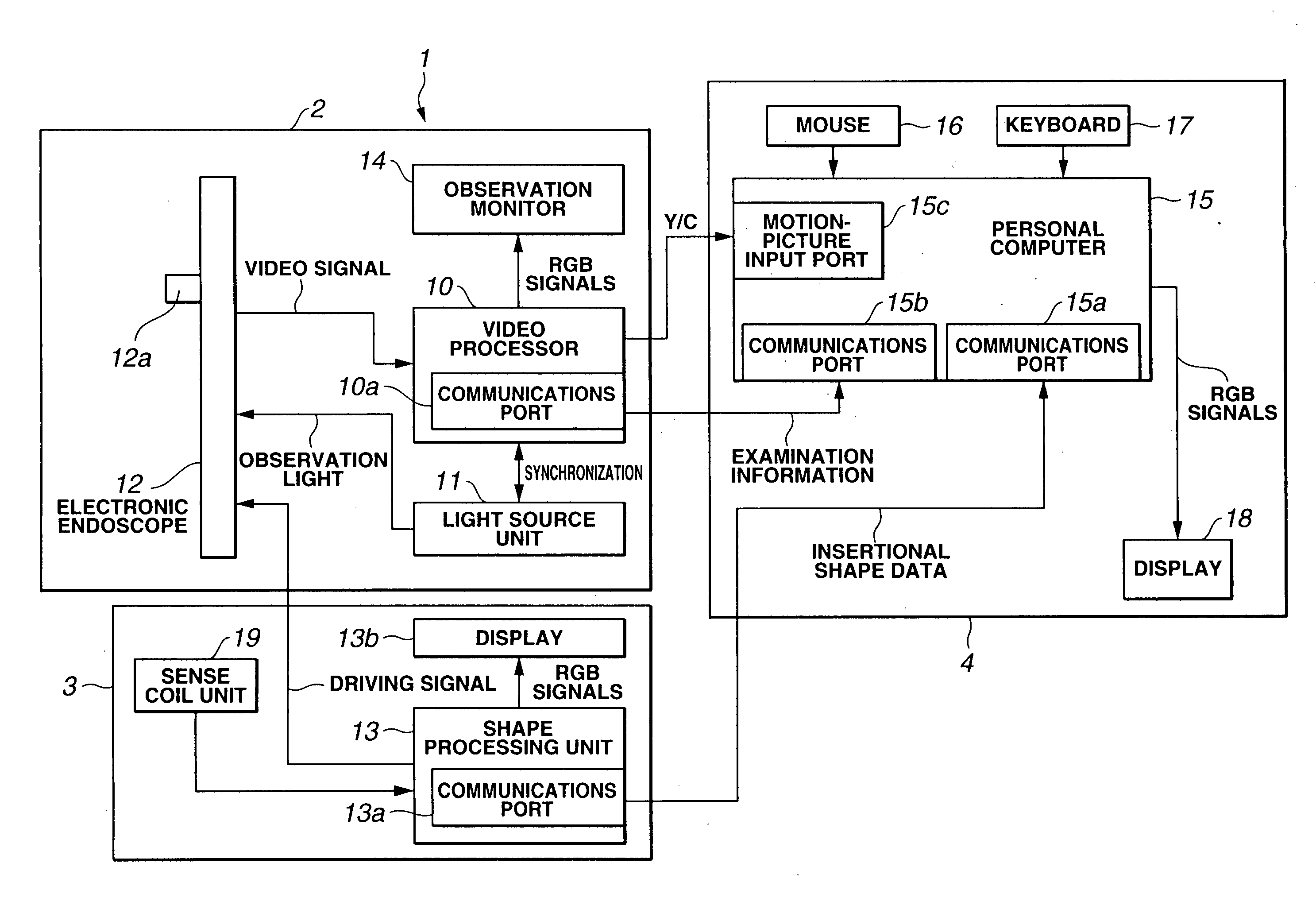
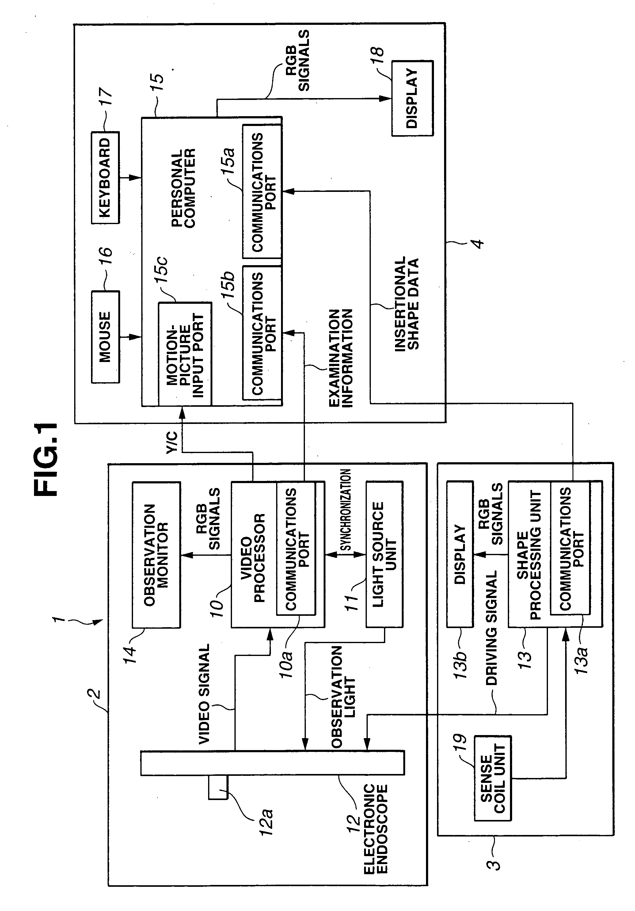
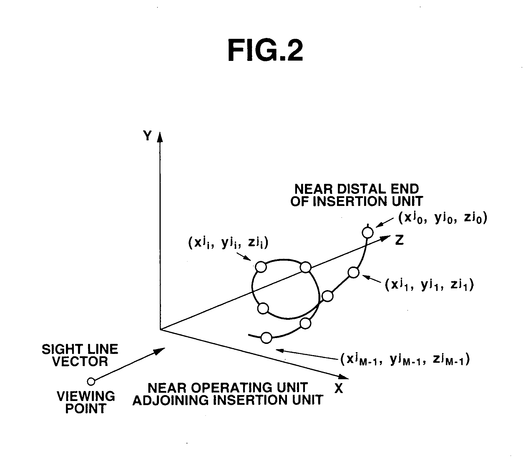
[0052] To begin with, the present invention will be described in conjunction with FIG. 1 to FIG. 6.

[0053]FIG. 1 is a block diagram showing the overall configuration of an electronic endoscopic system employing the first embodiment of the present invention. FIG. 2 is an explanatory diagram showing a coordinate system representing an inserted position to which an insertion unit included in the electronic endoscopic system employing the first embodiment is inserted. FIG. 3 is an explanatory diagram showing the data structure of inserted position detection data produced by an insertional shape-of-endoscope observing system included in the electronic endoscopic system employing the first embodiment. FIG. 4 is a flowchart describing a process to be executed in the electronic endoscopic system employing the first embodiment. FIG. 5 is a flowchart describing an operation of detecting a stretch made by an object that is provided by the electronic endoscopic system employing the first embodim...

second embodiment

[0106] Next, the present invention will be described in conjunction with FIG. 7 and FIG. 8.

[0107] The configuration of the electronic endoscopic system 1 employing the second embodiment is identical to that of the electronic endoscopic system employing the first embodiment. The image processing system 4 treats endoscopic image data received from the endoscope system 2 and insertional shape data received from the insertional shape-of-endoscope observing system 3 in fundamentally the same manner as the image processing system in accordance with the first embodiment.

[0108] A difference of the second embodiment from the first embodiment lies in the warning executed at step S10 in the image processing system 4. The warning executed at step S10 in the second embodiment comprises steps started with step S41 and described in FIG. 7.

[0109] At step S41, the PC 15 verifies whether insertional shape data relevant to a frame preceding the current frame that has relevant insertional shape data ...

third embodiment

[0121] Next, the present invention will be described in conjunction with FIG. 9 and FIG. 10.

[0122] The configuration of the electronic endoscopic system 1 employing the third embodiment is identical to that of the electronic endoscopic system employing the first embodiment. Moreover, the image processing system 4 treats an endoscopic image or insertional shape data received from the endoscope system 2 and insertional shape-of-endoscope observing system 3 respectively in fundamentally the same manner as that of the first embodiment.

[0123] A difference of the third embodiment from the first embodiment lies in detection to be performed when the insertion unit of the electronic endoscope 12 is inserted with the distal part of the insertion unit bent at an angle. If the endoscope insertion unit is inserted with the distal part thereof bent at an angle but the direction of insertion in which the endoscope insertion unit is inserted is not checked, it causes a patient or a subject discomf...


PUM


Abstract

An endoscopic information processing system in accordance with the present invention comprises: a shape analyzing unit that analyzes an insertional shape acquired by detecting the shape of an insertion unit of an endoscope which is inserted into a body cavity; and an information providing unit that provides information on the situation of handling the endoscope according to the result of the analysis performed by the shape analyzing unit.

Description

TECHNICAL FIELD [0001] The present invention relates to an insertional shape-of-endoscope analyzing system that analyzes the insertional shape of an endosdope insertion unit in a body cavity, displays an image according to the insertional shape information, and thus contributes to improvement in the insertional maneuverability of an endoscope. BACKGROUND ART [0002] In general, electronic endoscopes have an insertion unit that is elongated and flexible and that has an electronic image pickup device incorporated in the distal part thereof. The insertion unit is externally inserted into an object that is the lumen of a body cavity, and an image is reproduced on a monitor screen according to an image signal produced by the electronic image pickup device incorporated in the distal part of the insertion unit. The object is observed by viewing the reproduced image. Moreover, treatment forceps are passed through a forceps channel formed in the insertion unit, and used to collect a living ti...

Claims


Application Information

Patent Timeline
Patent Type & Authority Applications(United States)
IPC IPC(8): A61B1/005A61B19/00
CPCA61B1/00009A61B1/0005A61B1/00055A61B1/0051A61B5/062A61B5/7232A61B19/5212A61B19/5244A61B19/56A61B2019/5251A61B2019/562A61B19/52A61B90/36A61B34/20A61B34/25A61B90/361A61B2034/2051A61B2034/252
Inventor HIRAKAWA, KATSUMI
Owner OLYMPUS CORP
Why Eureka
Try Eureka