Communications device for remote control of rail track switches in a train yard

a technology for communication devices and rail tracks, applied in the direction of vehicle position/course/altitude control, process and machine control, instruments, etc., can solve the problems of requiring time-consuming and burdensome coordination, requiring activation of individual switches at a time may be rather cumbersome, and certain switches along a chosen route may not be available for us

Active Publication Date: 2005-10-13
GE GLOBAL SOURCING LLC
View PDF16 Cites 17 Cited by
  • Summary
  • Abstract
  • Description
  • Claims
  • Application Information

AI Technical Summary

Benefits of technology

[0010]FIG. 4 illustrates an exemplary embodiment wherein the communications device takes the form of one or more user interface devices positioned wayside in the yard, such as one or more user stationary interface panels strategically positioned throughout one or more zones in the train yard to be accessible to one or more operators working in the yard.

Problems solved by technology

Known train routing techniques at a train yard require access to and the use of separate communication devices, and further require time consuming and burdensome coordination among various personnel to ensure that an appropriate selection and activation of rail track switches is accurately performed to achieve a desired transfer or routing of a locomotive from a given location to a desired destination within the train yard.
In addition, requesting activation of an individual switch at a time may be rather cumbersome considering that in a typical train yard to reach a desired destination may involve activating a switching combination comprising a plurality of switches.
Moreover, because of other traffic in the railyard, certain switches along a chosen route may not be available for use.
Partial, and thus incomplete, movement of one locomotive may in turn interfere with the orderly movement of other locomotives in the yard.
Also user displays in known portable train routing devices for train yard operations are usually limited to alphanumeric characters, and thus may not fully achieve the simplicity of operation and user friendliness that would be desirable.

Method used


Image

  • Communications device for remote control of rail track switches in a train yard
  • Communications device for remote control of rail track switches in a train yard
  • Communications device for remote control of rail track switches in a train yard

Examples


Embodiment Construction

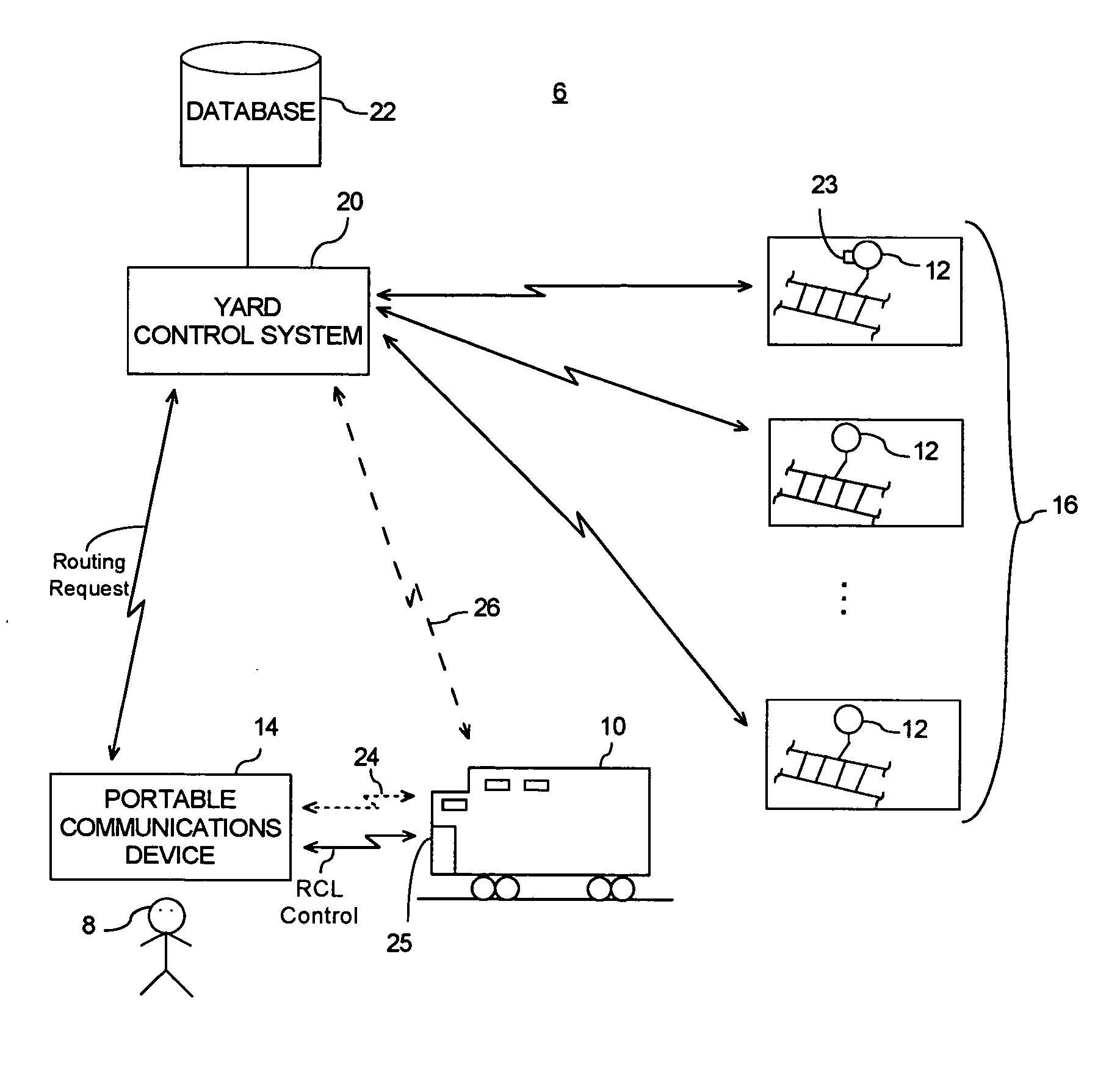
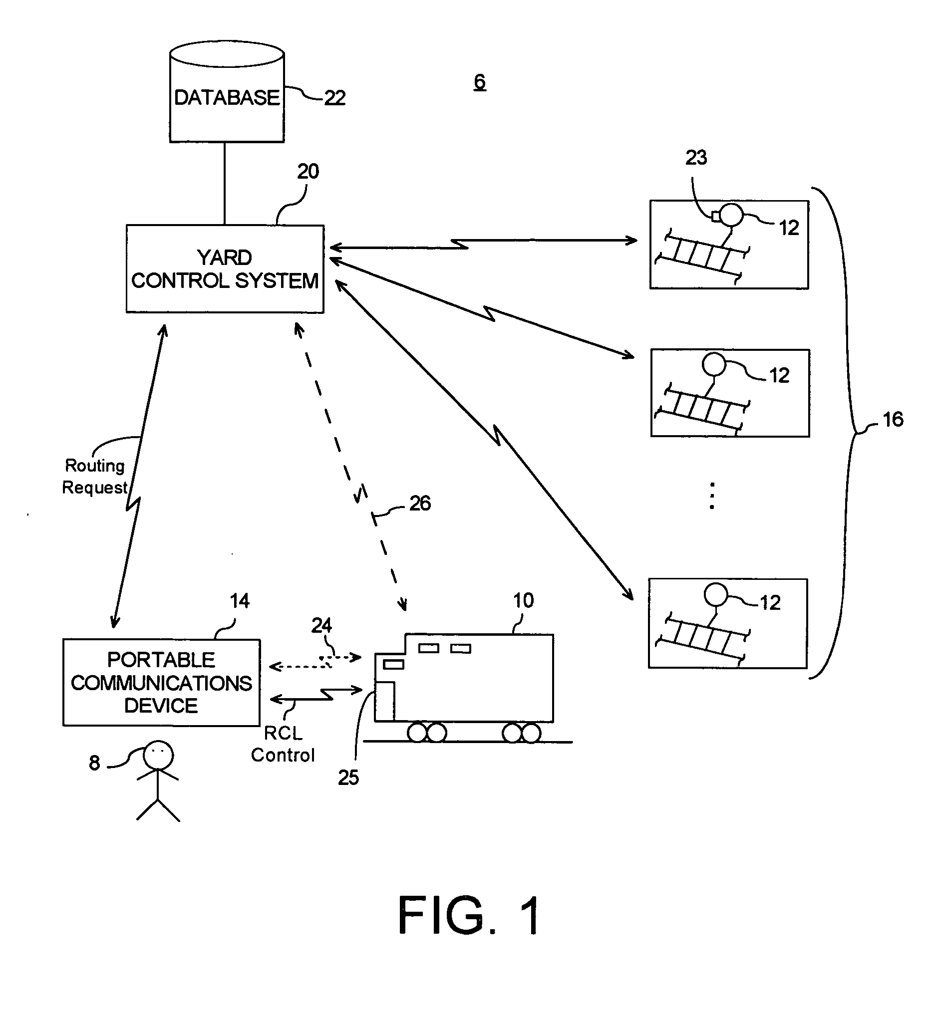
[0011] As illustrated in the schematic representation of FIG. 1, a command communication and control (CCC) train rail yard system 6 embodying aspects of the present invention provides to an operator 8 of a Remote Controlled Locomotive (RCL) 10 the ability to actuate combinations of one or more remote controlled track switches 12 via a portable communications device 14, such as an Operator Control Unit (OCU) that may be hand-held or otherwise supportable by the body of the operator. Portable communications device 14 also allows the operator to control movement of the locomotive 10. This provides operator 8 with the ability to command a switching strategy for routing the locomotive and also guiding the locomotive from any given track to any other track in a rail track layout 16 of the train yard.

[0012] As will be appreciated by those skilled in the art, a train yard may comprise a large number of inter-connectable rail tracks, which are connectable through the actuation of appropriat...


PUM


Abstract

A communications device is provided for routing a locomotive over a track layout in a train yard. The locomotive is operable over a plurality of alternative track routes to reach a respective destination from a plurality of possible destinations in said track layout. The track layout includes a plurality of switches configured to alter a route for a locomotive running along the track layout. The communications device may include a first user display for use in commanding a desired destination for the locomotive within the track layout by setting the state of the switches along the route to the destination.

Description

[0001] This application is a Continuation-In-Part, and claims filing date benefit, of U.S. application Ser. No. 10 / 759,319 filed Jan. 16, 2004, which in turn claims priority to a provisional application filed on Feb. 20, 2003, having application No. 60 / 448,701, and to a provisional application filed on Dec. 11, 2003, having application No. 60 / 528,862, each of which is incorporated herein by reference in their entirety.FIELD OF THE INVENTION [0002] The present invention is generally related to railroad communication devices, and, more particularly, to a communications device for remote control of rail track switches at a train yard. BACKGROUND OF THE INVENTION [0003] Known train routing techniques at a train yard require access to and the use of separate communication devices, and further require time consuming and burdensome coordination among various personnel to ensure that an appropriate selection and activation of rail track switches is accurately performed to achieve a desired ...

Claims


Application Information

Patent Timeline
Patent Type & Authority Applications(United States)
IPC IPC(8): B61L3/12B61L7/06B61L17/00
CPCB61L3/127B61L17/00B61L7/06
Inventor KORNICK, DAVIDFOY, ROBERT JAMESMOORE, ERIC B.MCELROY, JOHN WELSHLUEVANO, CHRISFREEMAN, GEORGE
Owner GE GLOBAL SOURCING LLC
Why Eureka
Try Eureka