

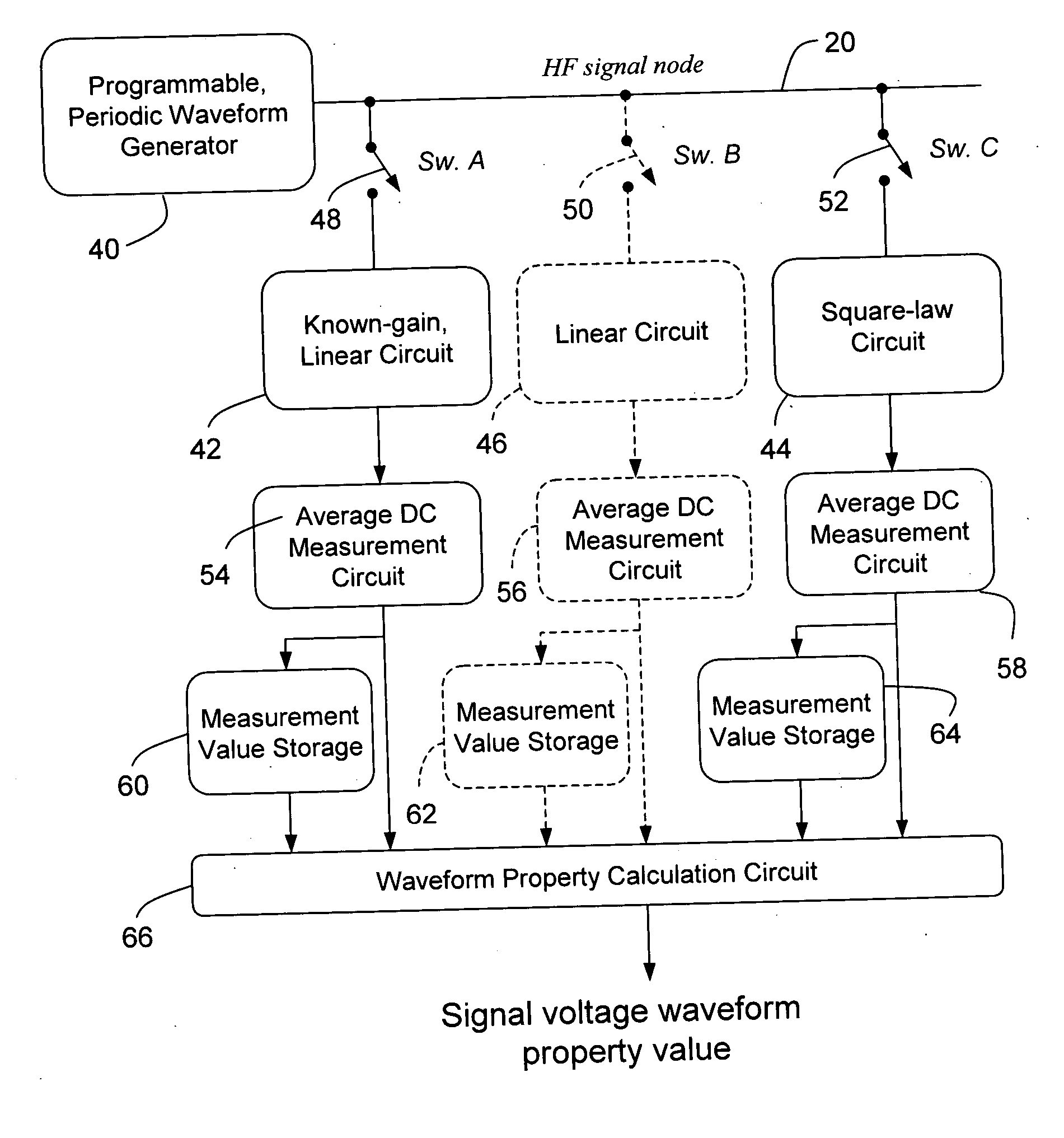
Circuit and method for low frequency testing of high frequency signal waveforms
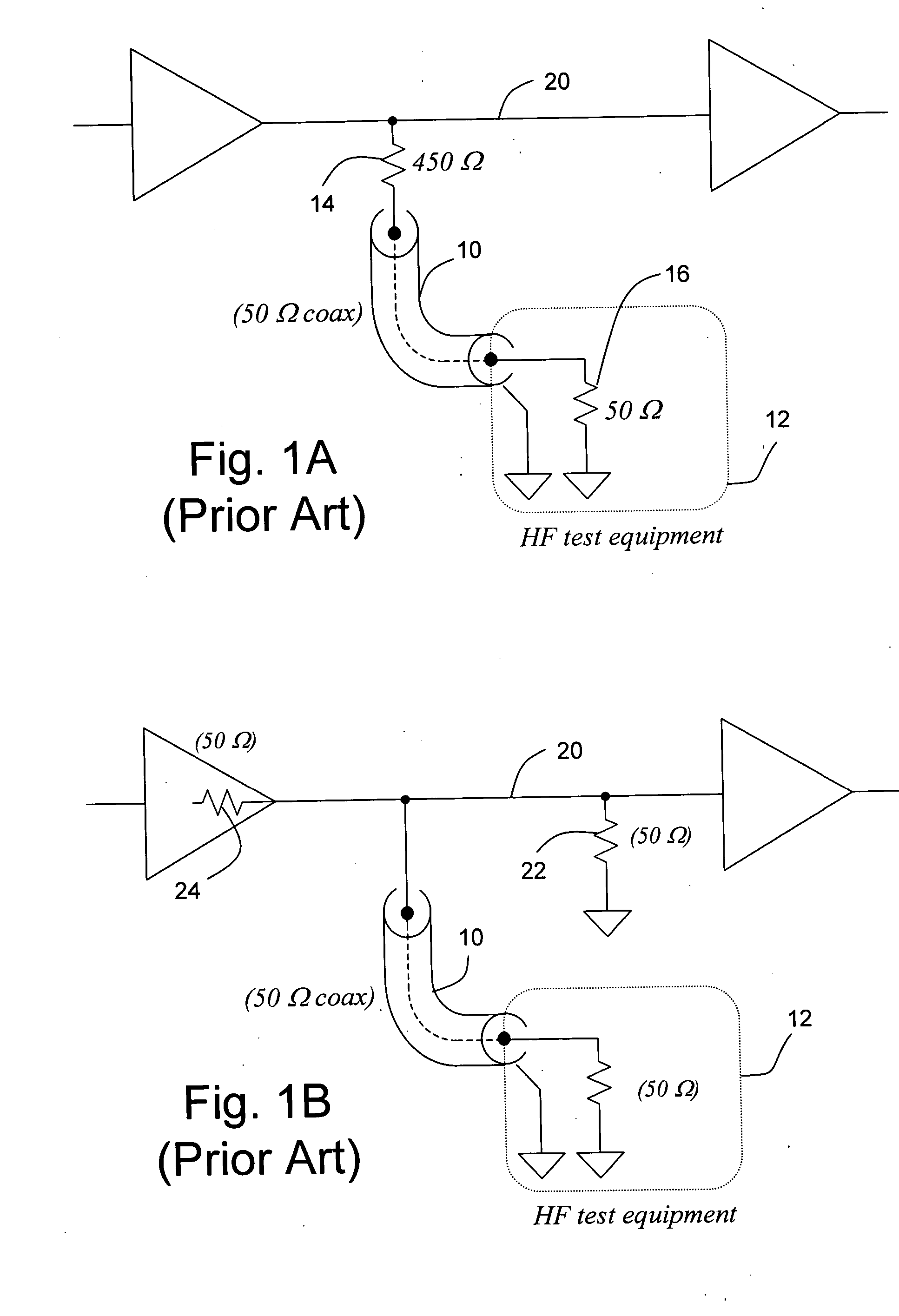
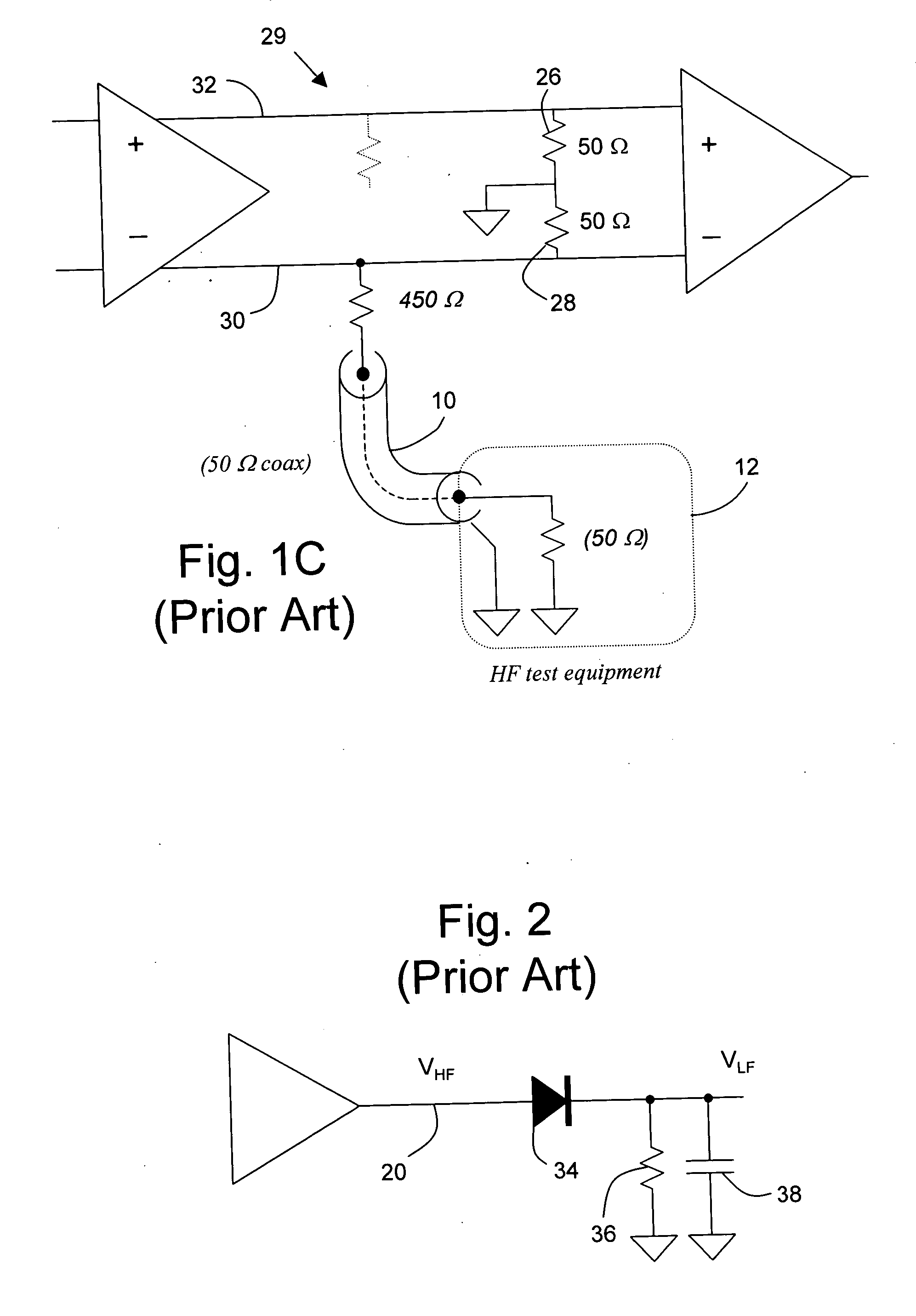
a high frequency signal and circuit technology, applied in the field of high frequency signal waveform parameters testing, can solve the problems of affecting the amplitude of the accessed signal, and the power level of the signal does not provide any information about the shape of the signal
- Summary
- Abstract
- Description
- Claims
- Application Information
AI Technical Summary
Benefits of technology
Problems solved by technology
Method used
Image

Examples
example calculations
[0063] Logic Level Voltage
[0064] To deduce the logic levels 146, 140, 148, 150 of a signal, a periodic data pattern is first generated containing a sequence of consecutive logic 1 bits, for example 1111000100, as shown in waveform 160, V1, of FIG. 10. The term “periodic” means that the same pattern is transmitted repeatedly and continuously, i.e., 11110001001111000100 . . . without any inserted pauses or other bits. The sequence is preferably isolated from other logic 1 bits in the periodic pattern, by two or more logic 0 bits, to minimize the impact of settling times. The average voltage, V1avg, of the signal is measured.
[0065] Next, a periodic data pattern is generated containing a sequence of consecutive logic 1 bits, where the number of consecutive logic 1 bits is different, for example one more logic 1 bit, as shown in the 1111100100 waveform 162, (V2), of FIG. 10. The average voltage, V2avg, of the signal is measured.
[0066] The voltage difference between the logic 1 voltage...
PUM
 Abstract
Description
Claims
Application Information