Multi-light-source illumination system for optical pointing devices

Active Publication Date: 2005-10-20
LOGITECH EURO SA
View PDF16 Cites 144 Cited by
  • Summary
  • Abstract
  • Description
  • Claims
  • Application Information

AI Technical Summary

Benefits of technology

[0017] According to the teachings of the present invention, in an optical pointing device for use with a computer system, one embodiment of an optical displacement detection system comprises a sensor assembly and a plurality of light sources. The sensor assembly includes an electromagnetic energy sensing module and a control logic module. The plurality of light sour

Problems solved by technology

For example, mechanical or opto-mechanical input devices have mechanical components that are more susceptible to breakdown, wear out, or clogging.
However, there is a lack of performance improvements directed to features o

Method used


Image

  • Multi-light-source illumination system for optical pointing devices
  • Multi-light-source illumination system for optical pointing devices
  • Multi-light-source illumination system for optical pointing devices

Examples


Embodiment Construction

[0036] The Figures (“FIG.”) and the following description relate to preferred embodiments of the present invention by way of illustration only. It should be noted that from the following discussion, alternative embodiments of the structures and methods disclosed herein will be readily recognized as viable alternatives that may be employed without departing from the principles of the claimed invention.

[0037] Reference will now be made in detail to several embodiments of the present invention, examples of which are illustrated in the accompanying drawings. It is noted that wherever practicable similar or like reference numbers may be used in the figures and may indicate similar or like functionality.

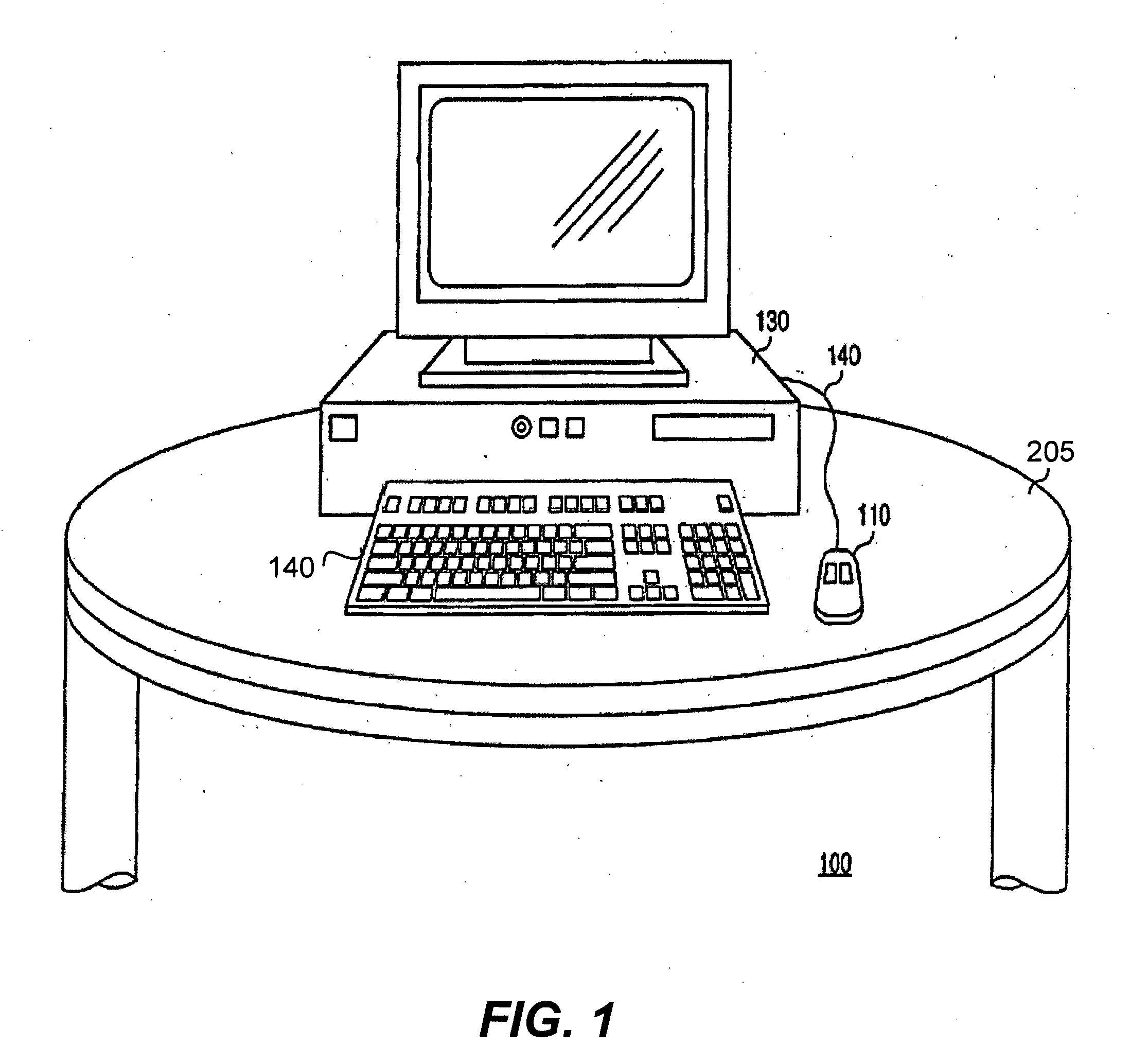
[0038]FIG. 3A illustrates a conventional optical mouse 110. The optical mouse is typically housed in an enclosure 310. Generally, the enclosures 310 are made of plastic materials and come in many shapes, e.g., ergonomic shapes, and colors. The optical mouse 110 connects to a computer 130...


PUM


Abstract

In one embodiment of an optical pointing device, an illumination system includes a plurality of light sources. Each light source is characterized by a unique set of illumination characteristics. Illumination characteristics include impinging angle, light wavelength, light homogeneity, and the like. A sensor receives electromagnetic energy originating at the light source to scan an imaged area. The sensor measures performance indexes associated with the light sources, which depend on the illumination characteristics. The sensor includes an imaging module, which may include passive filters, and control logic, which includes at least a DSP module and a light sensor selection module. Another embodiment includes additional signaling light sources that do not interfere with the illumination system and are for signaling to the user. A method to select the most adequate light source for any given surface is based on measured performance indices.

Description

CROSS REFERENCES TO RELATED APPLICATIONS [0001] This application is related to co-pending U.S. patent applications Ser. No. 10 / 033,427, filed on Dec. 27, 2001, and Ser. No. 10 / 122,488, filed on Apr. 12, 2002, both of which are incorporated herein by reference in their entirety.BACKGROUND OF THE INVENTION [0002] 1. Field of the Invention [0003] The present invention relates to electromagnetic energy sources for optical detection systems, more specifically, to multi-light-source optical input devices. [0004] 2. Description of the Related Art [0005] Displacement detection based on optical technology is used in several applications, including optical input devices for computer systems. Data processing systems, or computer systems generally, are used in conjunction with a variety of input devices, such as for example, keyboards, pointing devices (e.g., mice, touchpads, and trackballs), joysticks, digital pens, and the like. FIG. (“FIG.”) 1 shows a sample diagram of a conventional compute...

Claims


Application Information

Patent Timeline
IPC IPC(8): G06F3/00G06F3/03G06F3/033G09G5/08
CPCG06F3/03543G06F3/0317
Inventor THEYTAZ, OLIVIERMATHIS, OLIVIERMERMINOD, BAPTISTEEICHENBERGER, PASCAL
Owner LOGITECH EURO SA
Why Eureka
Try Eureka