Liquid ejecting apparatus and method for cleaning the same

Active Publication Date: 2005-10-20
SEIKO EPSON CORP
View PDF3 Cites 11 Cited by
  • Summary
  • Abstract
  • Description
  • Claims
  • Application Information

AI Technical Summary

Benefits of technology

[0006] It is therefore the first object of the present invention to provide a liquid ejecting apparatus capable of reducing invasion of a liquid between a liquid ejecting head and an inclined plate, further, when the liquid invades between the liquid ejecting head and the inclined plate, preventing the liquid from conducting to other portion.
[0007] Also, it is the second object of the present invention to provide a liquid ejecting apparatus and a cleaning method capable of restraining a liquid from being scattered by a wiping member which has finished wiping an opening portion of a nozzle to thereby less contaminate an inner portion thereof.

Problems solved by technology

In the above configuration, the opening portion of the space between the liquid ejecting head and the inclined plate is narrowed and therefore, it is difficult for the liquid to invade the space via the opening portion.

Method used


Image

  • Liquid ejecting apparatus and method for cleaning the same
  • Liquid ejecting apparatus and method for cleaning the same
  • Liquid ejecting apparatus and method for cleaning the same

Examples


first embodiment

[0099] A first embodiment of a liquid ejecting apparatus embodying the invention will be explained in reference to FIG. 1 through FIG. 4 as follows.

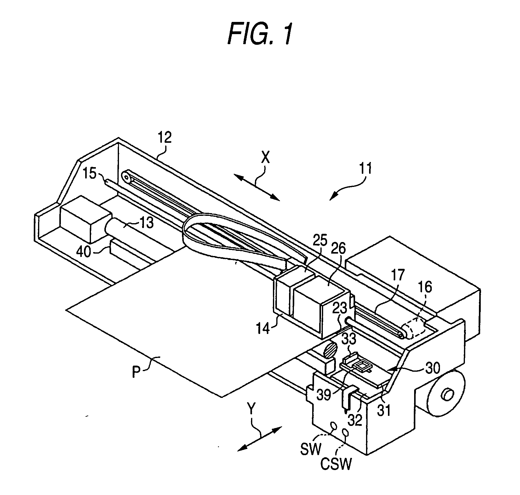
[0100] As shown in FIG. 1, according to an ink jet type printer 11 (hereinafter, referred to as printer) as a liquid ejecting apparatus of the present invention, a platen 13 is mounted on a frame 12 thereof and paper P as a target is fed onto the platen 13 by a paper feeding mechanism, not illustrated. A carriage 14 is supported by the frame 12 movably in an axial direction of the platen 13 via a guide member 15 and is reciprocated in X direction (horizontal direction) by a carriage motor 16 via timing belt 17.

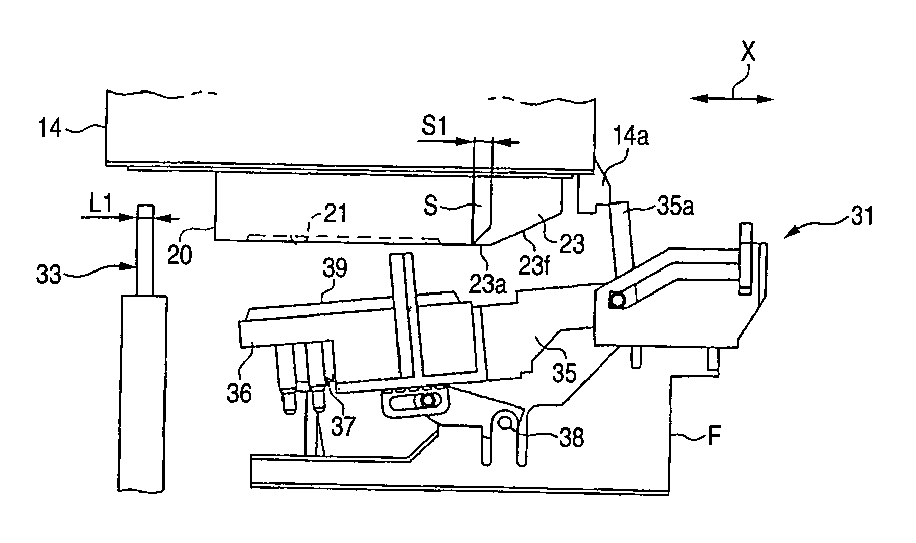
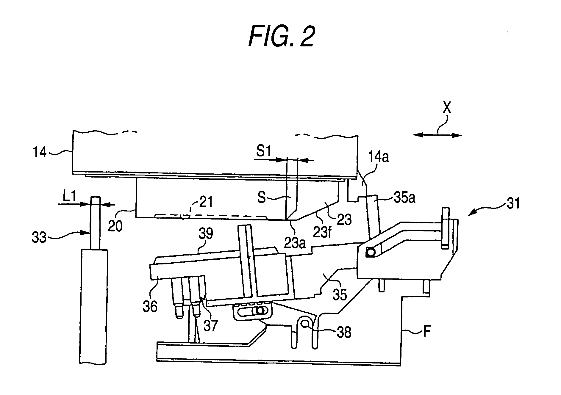
[0101] Further, as shown in FIG. 2, a recording head 20 as a liquid ejecting head is mounted on the carriage 14. The recording head 20 has a plurality of nozzles and provided with a nozzle plate portion 21 at which respective opening portions of the nozzles are gathered at a center of a lower face thereof. The recording head 20 e...

second embodiment

[0120] Next, the printer 11 as a liquid ejecting apparatus of a second embodiment embodying the present invention will be explained in reference to FIG. 5. Further, in the following respective embodiments, the same notations are attached to portions similar to those of the embodiment and a detailed explanation thereof will be omitted. Further, according to the second embodiment, only a portion related to the recording head 20 and the inclined plate 23 is different from that of the first embodiment.

[0121] As shown in FIG. 5, on the left side of the inclined plate 23, rib portions 23b and 23c having a width the same as a width in Y direction thereof (in FIG. 5, direction orthogonal to paper face) are provided at an interval. The rib portion 23b is provided at the lowermost portion on the side of the recording head 20 in place of the projected portion 23a of the first embodiment. Further, on the right side of the recording head 20, a rib portion 20a having a width the same as the widt...

third embodiment

[0127] Next, a printer as a liquid ejecting apparatus of a third embodiment embodying the invention will be explained in reference to FIG. 6.

[0128] According to the embodiment, as shown in FIG. 6, a lower end portion of the inclined plate 23 on the side of the recording head 20 is formed with a holding projection 23d in place of the projected portion 23a of the first embodiment. Further, the inclined plate 23 is provided at the carriage 14 such that the holding projection 23d is disposed at a height substantially the same as that of the lower face of the recording head 20.

[0129] Further, the space S is arranged with a sponge 27 as an absorbing member at the space S between the recording head 20 and the inclined plate 23. The sponge 27 includes a porous material of sponge or the like and is formed in a trapezoidal shape having a lower side a sectional shape in a free state of which is large. Therefore, the sponge 27 is supported by the holding projection 23d in a state of contracti...


PUM


Abstract

A liquid ejecting apparatus includes a liquid ejecting head having a plurality of nozzles for ejecting a liquid drop formed at a lower face thereof, a wiping member wiping an opening portion of the nozzle, a carriage mounted with the liquid ejecting head, and moving in a horizontal direction relative to the wiping member; and an inclined plate mounted on the carriage at a predetermined space from the liquid ejecting head, and formed with an inclined face having a rising inclination as being far from the liquid ejecting head. A projected portion is provided on at least one of the liquid ejecting head and the inclined plate such that an opening portion at a lower side of the space is smaller than an upper portion of the space.

Description

BACKGROUND OF THE INVENTION [0001] The present invention relates to a liquid ejecting apparatus and a cleaning method thereof, particularly, relates to a liquid ejecting apparatus in which a liquid ejecting head is mounted on a carriage, and the liquid ejecting head ejects a liquid to a target by moving the carriage relative to the target and a cleaning method for cleaning the liquid ejecting apparatus. [0002] For example, there is an ink jet type printer for printing by ejecting a plurality of ink drops as an apparatus for ejecting an extremely small amount of a liquid to a target. The printer of this kind is provided with a recording head formed with a plurality of nozzles each having a very small opening portion and each ink drop is ejected from the opening portion of each nozzle. Further, the printer is provided with a wiping member for maintenance cleaning. In finishing the maintenance cleaning, the wiping member slides on a lower face of the recording head so that ink adhered ...

Claims


Application Information

Patent Timeline
IPC IPC(8): B41J2/165
CPCB41J2/16535
Inventor TSUKADA, KENJI
Owner SEIKO EPSON CORP
Why Eureka
Try Eureka