Hydrostatic transaxle apparatus

a transaxle and hydrostatic technology, applied in the direction of belts/chains/gearrings, fluid couplings, gearings, etc., can solve the problems of increasing the number of parts and costs, complicated center sections for fluidly connecting the hydraulic pump and the motor to each other, and the obstacle to minimization of the iht, so as to achieve the effect of reducing the hydrostatic transaxle and simple and economical configuration of the hs

Inactive Publication Date: 2005-10-20
OKADA HIDEAKI +1
View PDF13 Cites 0 Cited by
  • Summary
  • Abstract
  • Description
  • Claims
  • Application Information

AI Technical Summary

Benefits of technology

[0009] An object of the present invention is to provide a greatly minimized hydrostatic transaxle apparatus which may especially serve as an IHT for a vehicle having a vertical crankshaft engine, wherein a simple and economical configuration of an HST is secured. The hydrostatic transaxle apparatus comprises a housing filled therein with fluid so as to serve as a fluid sump, an axle disposed in the housing, a hydraulic pump disposed in the housing to be drivingly connected to a prime mover, a hydraulic motor disposed in the housing to be drivingly connected to the axle, and a center section disposed in the housing to fluidly connect the hydraulic pump and motor to each other.

Problems solved by technology

However, the configuration of a center section for fluidly connecting the hydraulic pump and motor to each other must be complicated.
This is an obstacle to minimization of the IHT in the radial direction of the HST.
Further, for positioning the rotors and track rings, the plate to be sandwiched between the hydraulic pump and motor must be provided around the pintle, thereby increasing the number of parts and costs.

Method used


Image

  • Hydrostatic transaxle apparatus
  • Hydrostatic transaxle apparatus
  • Hydrostatic transaxle apparatus

Examples


first embodiment

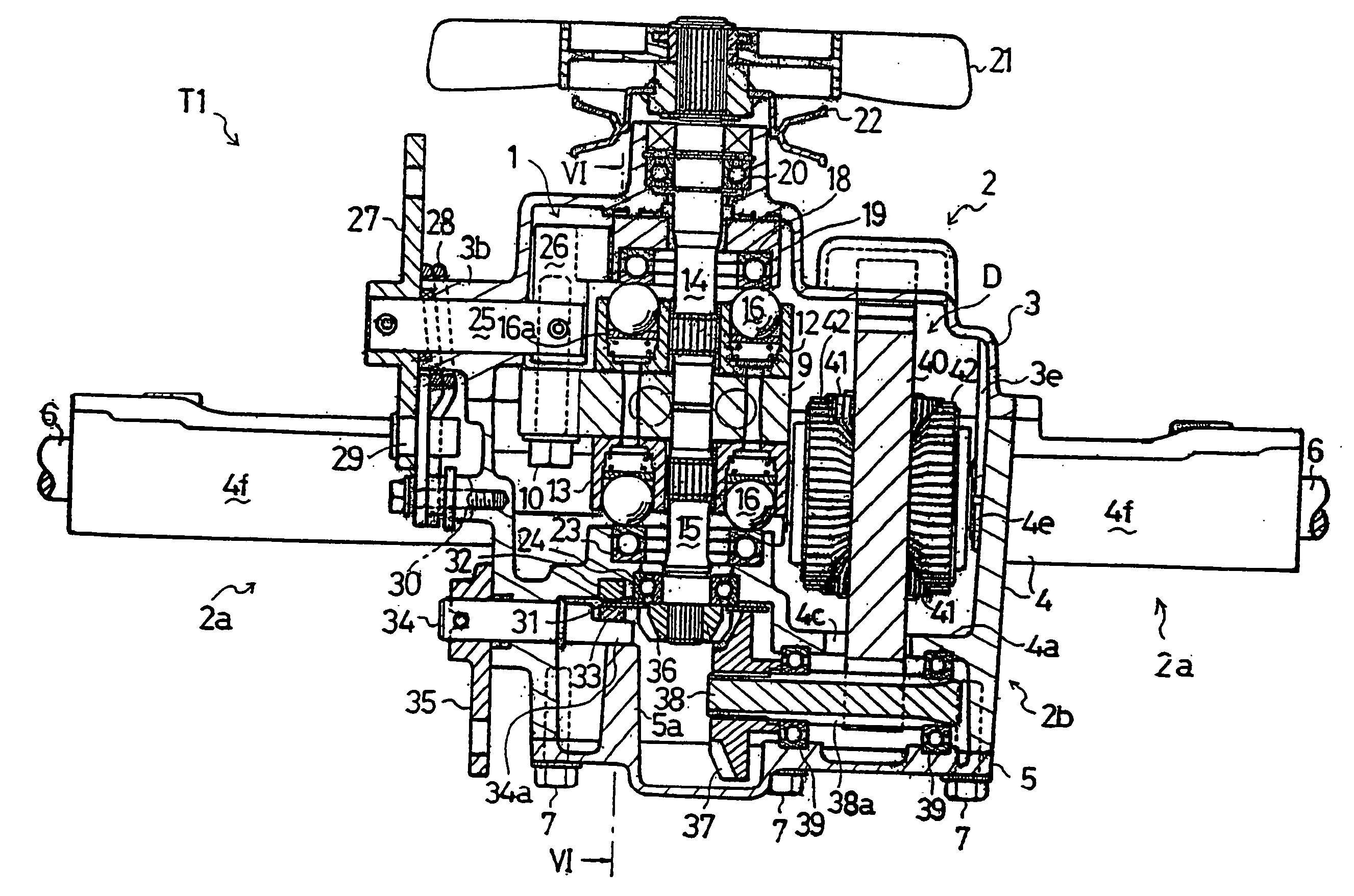
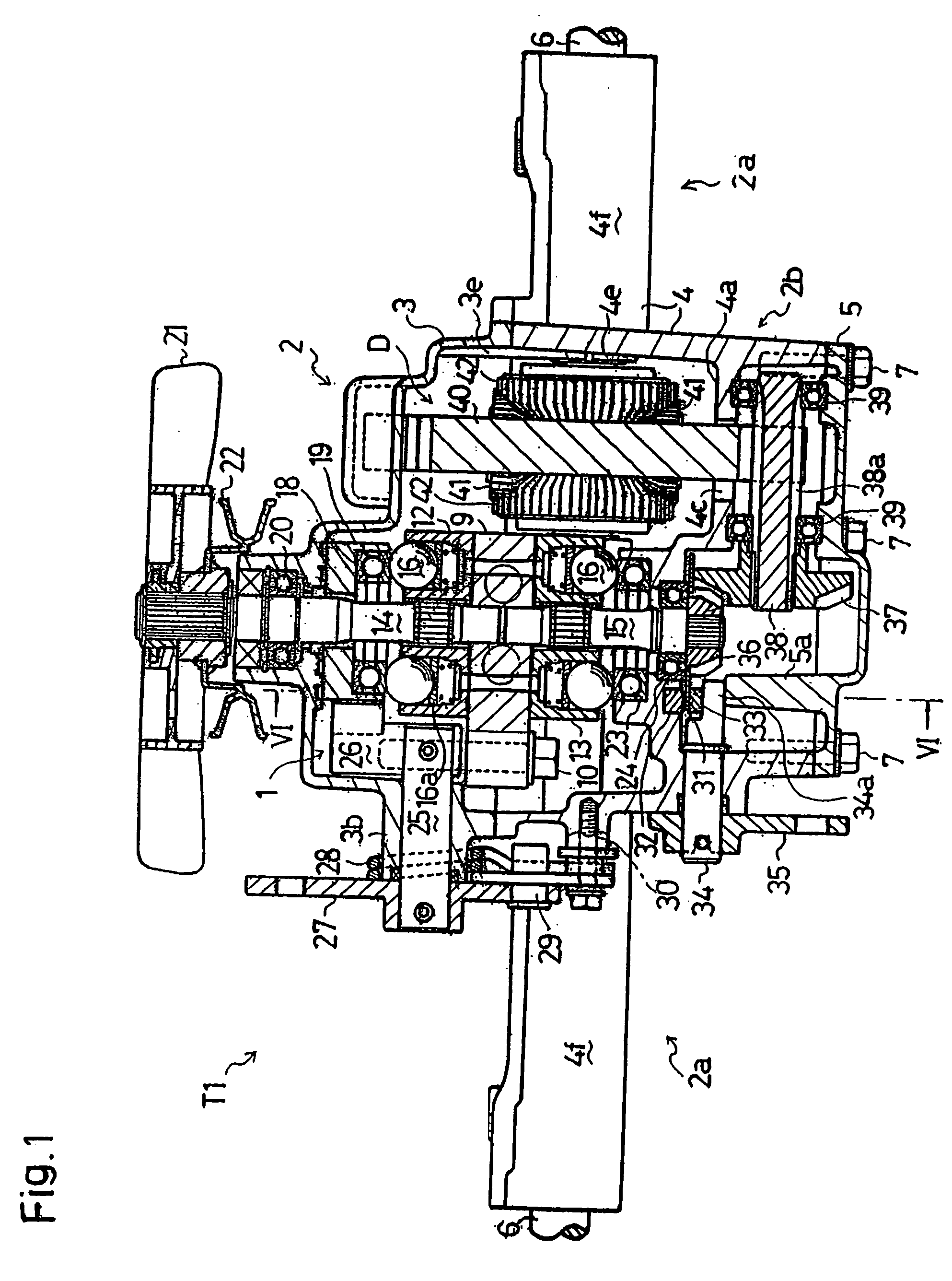
[0061] Description will be given of a hydrostatic transaxle apparatus TI serving as the present invention in accordance with FIGS. 1 to 7. A transaxle housing 2 of hydrostatic transaxle apparatus Ti consists of top, middle and bottom housing members 3, 4 and 5 joined to one another. A pair of left and right axles 6 are coaxially disposed horizontally and journalled by middle housing member 4. Above axles 6, top and middle housing members 3 and 4 are jointed to each other through a substantially horizontal surface J along axes of axles 6 by bolts 7 (See e.g. FIG. 5). Below axles 6, middle and bottom housing members 4 and 5 are jointed to each other through a substantially horizontal surface along the axes of axles 6 by bolts 7. (See e.g. FIG. 6)

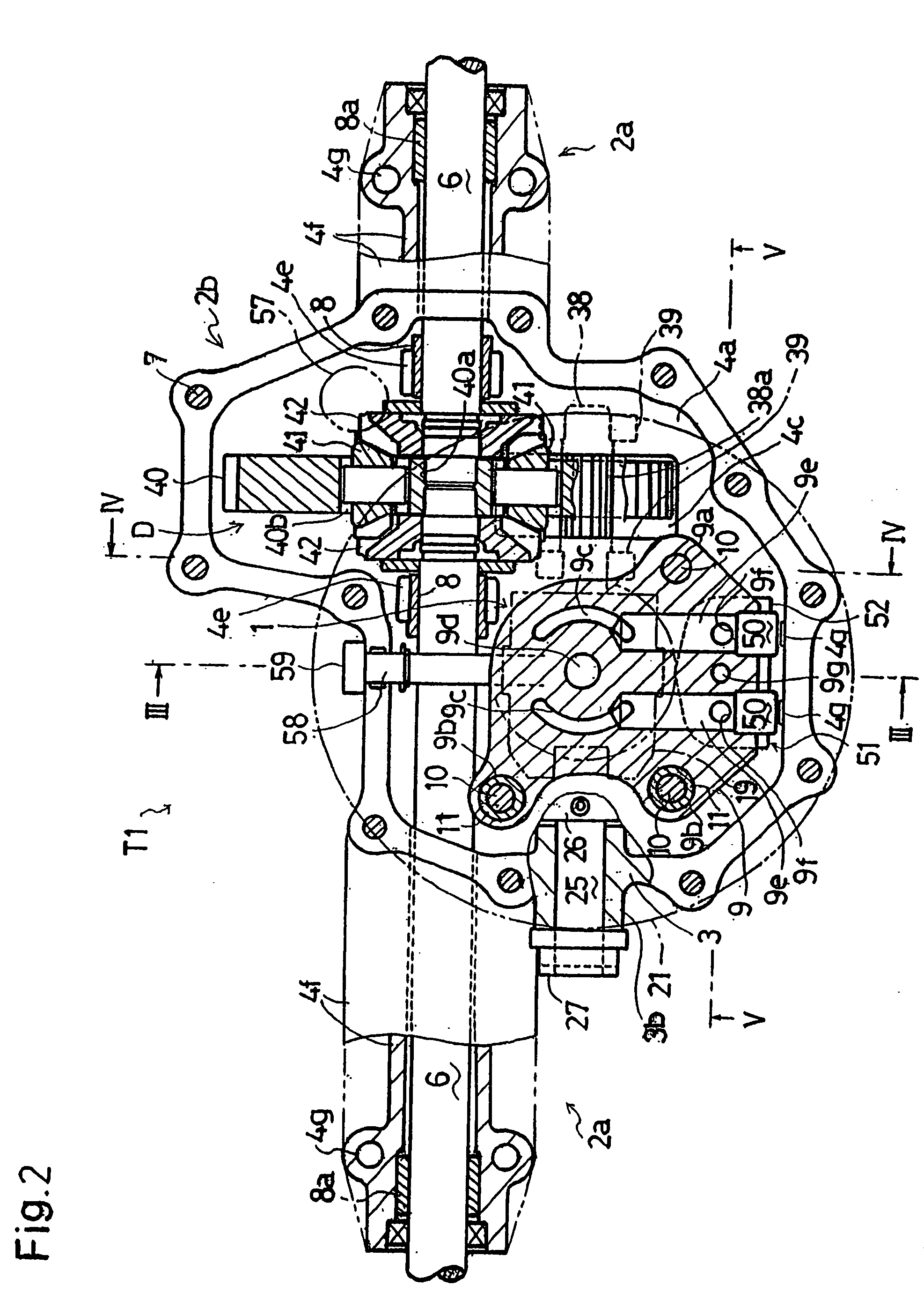
[0062] As shown in FIG. 4, for journalling each axle 6 disposed below joint surface J, bearings 8 and 8a are provided on axle 6. Bearing 8 is disposed adjacently to each of later-discussed differential bevel side gears 42 of a differential gea...

second embodiment

[0106] Description will now be given of a hydrostatic transaxle apparatus T2 as the invention in accordance with FIGS. 8 to 10, only referring to members and portions which are different from those of hydrostatic transaxle apparatus T1 shown in FIGS. 1 to 7. The same reference numerals as those in FIGS. 1 to 7 designates members and portions which are identical or similar to the above-mentioned ones.

[0107] Transaxle housing 2 of hydrostatic transaxle apparatus T2 consists of a pair of upper and lower housing members 62 and 63 joined to each other through horizontal joint surface J. Upper housing member 62 substantially equals to the above-mentioned top housing member 3. Lower housing member 63 substantially equals to middle and bottom housing members 4 and 5 integrated with each other. Particularly, upper and lower housing members 62 and 63 journals axles 6 through bearings 8 and 8a in the same way with that of top and middle housing members 3 and 4 for journaling axles 6. That is, ...

third embodiment

[0118] Description will be given of a transaxle apparatus T3 shown in FIGS. 12 and 13 as the present invention. This is the same with hydrostatic transaxle apparatus T2 except that relief valves for shock absorbing in stopping and starting of a vehicle are attached to oil charge assembly 50 and the arrangement of center section 9 and the shapes of housing members 62 and 63 are changed in connection with the relief valves.

[0119] In hydrostatic transaxle apparatus T2, the height of center section 9 in relative to housing 2 is established so as to make horizontal joint surface J between upper and lower housing members 62 and 63 divide the outer end openings of oil passages 9e vertically. However, in hydrostatic transaxle apparatus T3, center section 9 is so arranged as to make the heights of the bottom ends of the outer end openings of oil passages 9e substantially coincide with the height of horizontal joint surface J. Also, the inside surface of upper hosing member 62 facing to the o...


PUM


Abstract

A hydrostatic transaxle apparatus comprises a housing in which an HST, a pair of axles, a differential unit differentially connecting the axles to each other, and a horizontal counter shaft interposed between the HST and the differential unit. The HST comprises axial piston type hydraulic pump and motor mounted on vertically opposite surfaces of a center section, respectively, so as to be fluidly connected to each other so that pump and motor shafts are disposed vertically coaxially to each other. The center section is disposed adjacently to the differential unit and one of the axles. A cooling fan is fixed on the pump shaft projecting outward from the housing. When along the pump shaft, most of the housing except portions thereof for housing the respective axles is disposed within an area of rotary locus of the cooling fan.

Description

CROSS-REFERENCE TO RELATED APPLICATIONS [0001] This application is a continuation of U.S. application Ser. No. 10 / 755,368, filed Jan. 13, 2004, which is a continuation of U.S. application Ser. No. 10 / 157,963, filed May 31, 2002, now U.S. Pat. No. 6,682,453, issued Jan. 27, 2004, the entire disclosures of which are hereby incorporated by reference.BACKGROUND OF THE INVENTION [0002] 1. Field of the Invention [0003] The present invention relates to a hydrostatic transaxle apparatus, especially, for a vehicle having a vertical crankshaft engine. [0004] 2. Background Art [0005] A hydrostatic transaxle apparatus called an IHT comprises a hydrostatic transmission (hereinafter, referred to as an “HST”), an axle and a drive train interposed between the HST and the axle disposed together in a common housing. Some of various IHTs are used for a vehicle having a vertical crankshaft engine, wherein the rotary axis of the hydraulic pump of the HST must be disposed vertically, i.e., in perpendicul...

Claims


Application Information

Patent Timeline
Patent Type & Authority Applications(United States)
IPC IPC(8): F16H39/04F16H39/08F16H39/14F16H47/04
CPCF16H39/14
Inventor OKADA, HIDEAKIIIDA, MASARU
Owner OKADA HIDEAKI
Why Eureka
Try Eureka