Magnetic strainer

a strainer and magnetic technology, applied in the field of magnetic strainers, can solve the problems of rust on the aged pipe, measurement errors (slips), and iron powder is necessarily generated, and achieve the effects of abundant technology diversity, more economical and simple configuration, and abundant technology diversity

Active Publication Date: 2020-08-04
LEE SANG MOO +1
View PDF8 Cites 0 Cited by
  • Summary
  • Abstract
  • Description
  • Claims
  • Application Information

AI Technical Summary

Benefits of technology

[0010]Accordingly, the present invention has been made in view of the above-mentioned problems occurring in the prior art, and it is an object of the present invention to provide a magnetic strainer that is more economical and simple in configuration and has abundant technology diversity.
[0011]It is another object of the present invention to provide a magnetic strainer that basically prevents conductors like iron powder from being introduced in pipe components by means of magnetic forces of magnets, thereby maintaining the performance of the pipe components, extending their life span, and reducing their failure rate.
[0012]It is yet another object of the present invention to provide a magnetic strainer that easily discharges conductors attached to magnets of a filter member from a filter insertion hole through a discharge hole or easily separates the filter member to conveniently remove the conductors collected on the magnets.

Problems solved by technology

On construction in which a pipe like a water pipe is newly built or the pipe is repaired, iron powder is necessarily generated, and rust occurs on an aged pipe.
In case of the water pipe, in detail, the iron powder is attached to a magnet part as a transmission medium of an indicating part through a rotation part of an impeller as an important part of a large-sized water meter, thereby causing measuring errors (slip).
In case of an industrial pipe, further, the iron powder gives damages to main components like a pump and a solenoid or causes their failure, and besides, a quality of water becomes bad due to rusty water.

Method used


Image

  • Magnetic strainer
  • Magnetic strainer

Examples


Embodiment Construction

[0020]Hereinafter, an explanation on a magnetic strainer according to the present invention will be in detail given with reference to the attached drawings.

[0021]According to the present invention, the magnetic strainer is used in various kinds of pipes such as water pipes, boiler pipes, and so on, and especially, if the magnetic strainer is used in an old rotted pipe, it can effectively collect and discharge rust flowing along the pipe. The features of the present invention are as follows.

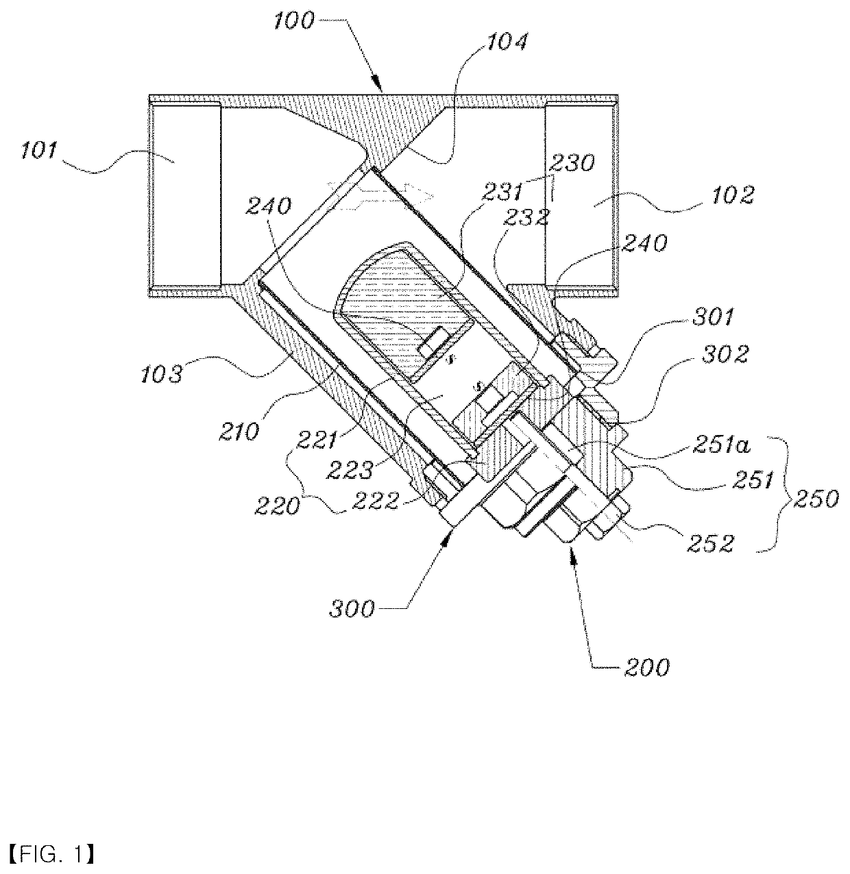
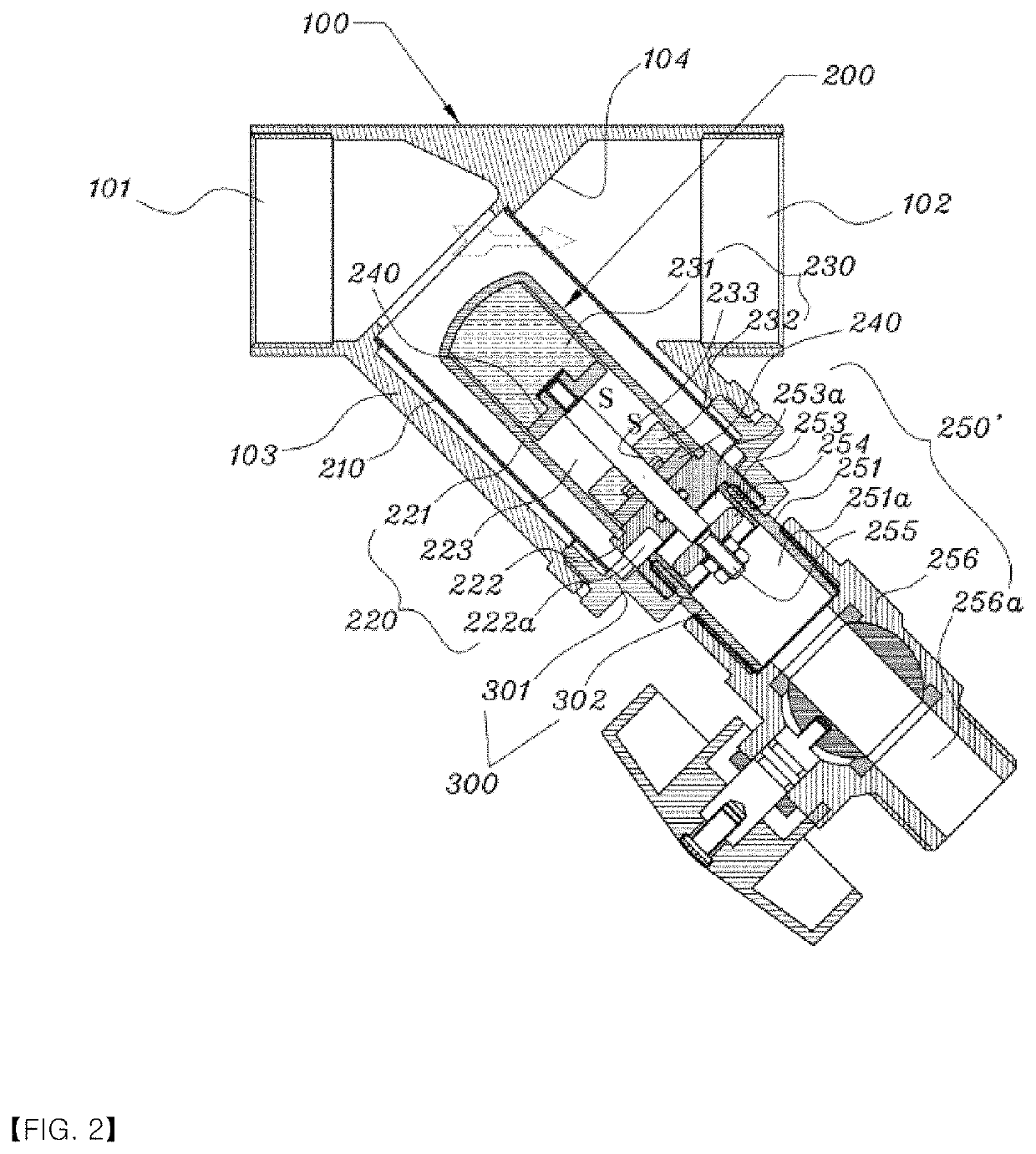
[0022]As shown in FIGS. 1 and 2, the magnetic strainer 1 according to the present invention includes an ‘Y’-shaped branch pipe 100 disposed on a line of a pipe and having an inlet 101 and an outlet 102 formed on both ends thereof and a filter insertion hole 103 formed unitarily on the center thereof, a cap 300 screw-fastened to the filter insertion hole 103 of the branch pipe 100, and a filter member 200 disposed in the filter insertion hole 103 in such a manner as to be coupled to the cap 300.

[00...


PUM

PropertyMeasurementUnit
specific gravityaaaaaaaaaa
pressureaaaaaaaaaa
diameteraaaaaaaaaa

Abstract

The present invention relates to a magnetic strainer that is configured to have a cap disposed in a filter insertion hole formed on the center of a branch pipe having an inlet and an outlet coupled to a pipe and to have upper and lower magnets arranged with repulsive forces, while placing a repulsive space therebetween, in such a manner as to be accommodated in both ends of a magnet case in a longitudinal direction of the magnet case to allow conductors in impurities to be easily collected to the inside of a filtering screen disposed between the filter insertion hole and the cap to filter the impurities, so that if ascending and descending means disposed under the magnet case operates, the upper magnet is descended to the repulsive space to easily remove the conductors collected on the top end surface of the magnet case.

Description

BACKGROUND OF THE INVENTIONField of the Invention[0001]The present invention relates to a magnetic strainer, and more particularly, to a magnetic strainer that is configured to have a cap disposed in a filter insertion hole formed on the center of a branch pipe having an inlet and an outlet coupled to a pipe and to have upper and lower magnets arranged with repulsive forces, while placing a repulsive space therebetween, in such a manner as to be accommodated in both ends of a magnet case in a longitudinal direction of the magnet case to allow conductors in impurities to be easily collected to the inside of a filtering screen disposed between the filter insertion hole and the cap to filter the impurities, so that if ascending and descending means disposed under the magnet case operates, the upper magnet is descended to the repulsive space to easily remove the conductors collected on the top end surface of the magnet case.Background of the Related Art[0002]On construction in which a p...

Claims


Application Information

Patent Timeline
Patent Type & Authority Patents(United States)
IPC IPC(8): B03C1/031B01D35/02E03B7/07
CPCB01D35/02B03C1/031E03B7/07B01D29/117B01D35/06B01D35/16B03C1/0332B03C1/286B03C1/30B03C2201/18B03C2201/28E03B7/074B01D35/28
Inventor LEE, SANG MOOPARK, DAE HO
Owner LEE SANG MOO
Why Eureka
Try Eureka