Electrosurgical cutting and cauterizing device

a technology of electrosurgical and cauterization device, which is applied in the field of radio frequency electrosurgical device, can solve the problems of reducing the effectiveness of the surgical device, inconvenience for surgeons, and low efficiency and power of the device, and achieves the effect of reducing the amount of external circuit elements, reducing power requirements, and increasing the efficiency of the uni

Inactive Publication Date: 2005-10-20
SPEARS MICHAEL
View PDF10 Cites 52 Cited by
  • Summary
  • Abstract
  • Description
  • Claims
  • Application Information

AI Technical Summary

Benefits of technology

[0012] This object is accomplished by use of a single, center-tapped coil wrapped around a carefully designed core and a capacitor, all contained within the hand-held unit. The core provides a field focusing agent. The reduction in the amount of external circuit elements increases the efficiency of the unit and reduces its power requirements.

Problems solved by technology

Therefore the efficiency and power of the device are low.
The patent states in two places that it is desirable rotto have a coil in the operative field of the device, as this causes inconvenience to the surgeon.
Unfortunately, both impedance matching and field focusing are dependent upon location and geometry.
The field both attenuates and spreads over the distance from this circuitry to the cutting tip, reducing the effectiveness of the surgical device.
Second, every component in the equipment results in losses, driving up power requirements, and every component must be accounted for in impedance matching and transmission line effects.
Until now, no one has accomplished good impedance matching and field focusing with circuitry housed within the handheld unit of an RF electrosurgical cutting and cauterizing device.

Method used


Image

  • Electrosurgical cutting and cauterizing device
  • Electrosurgical cutting and cauterizing device
  • Electrosurgical cutting and cauterizing device

Examples


Embodiment Construction

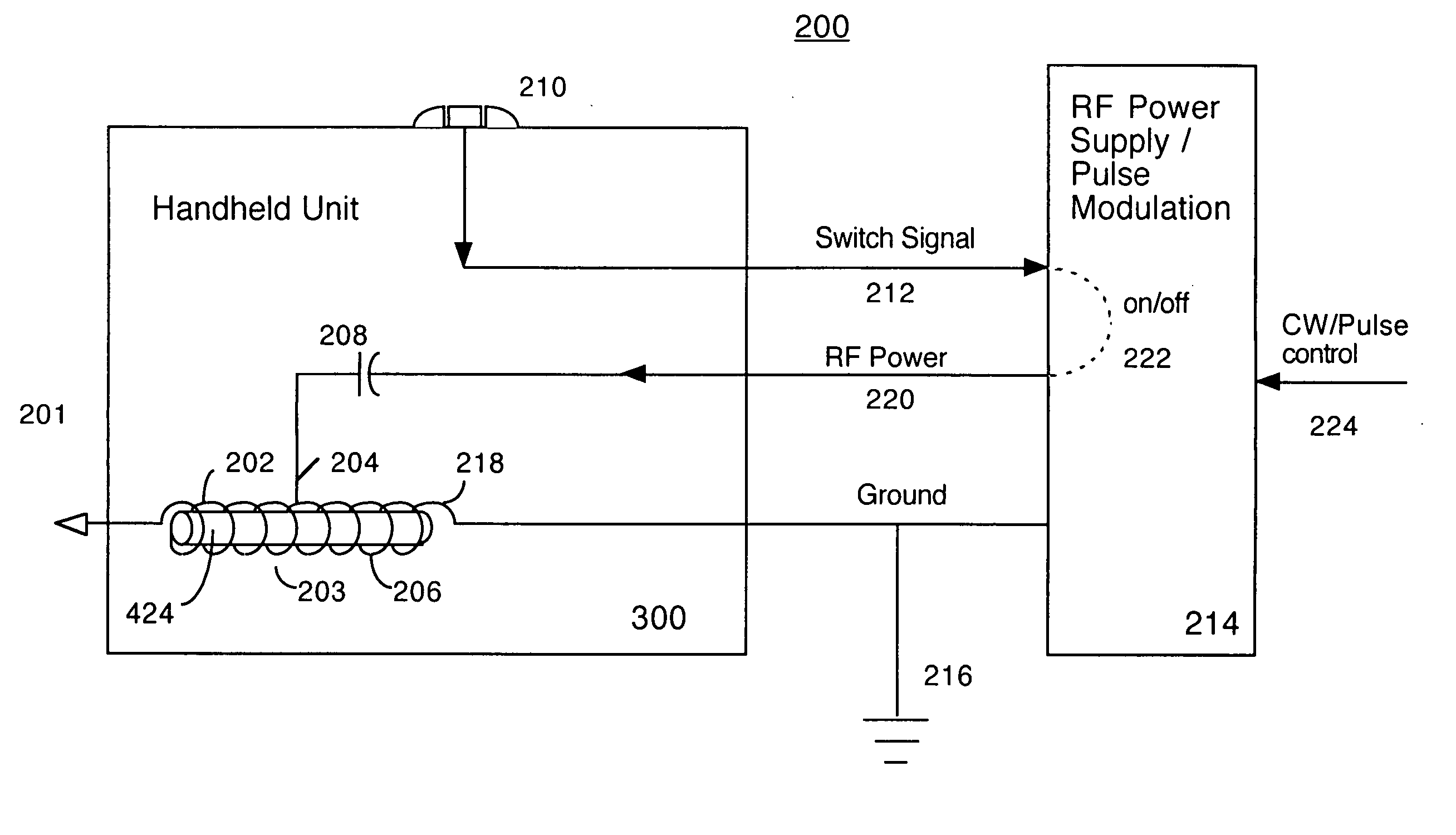
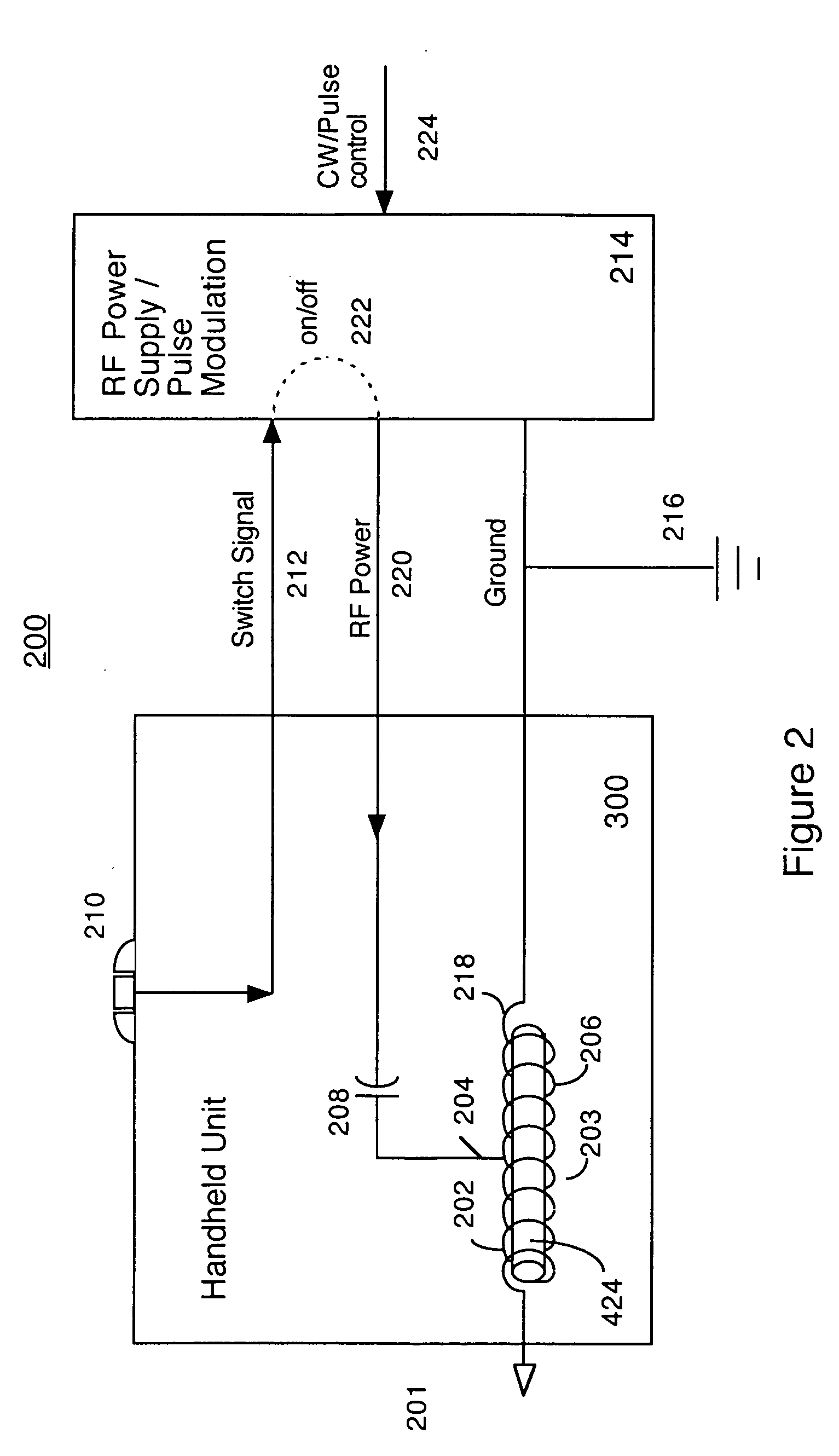
[0024]FIG. 2 shows the entire electrosurgical unit, including handheld element 300 and power supply 214. FIG. 3 shows the tip end of the handheld unit in detail. FIG. 4 shows the entire handheld unit, and FIG. 5 shows the connector end of the handheld unit in detail. FIG. 6 shows the connector in detail. FIG. 7 is an exploded view showing how the handheld unit goes together. FIGS. 8a and 8b show the coil connection element. FIG. 9 shows another embodiment of the electrosurgical device with a three position switch. Note that the terms “cutting,”“cutting device,” and “cutting tip” are used herein for convenience, but unless otherwise indicated are intended to include all the modes of the electrosurgical device: cutting, cauterizing, tissue reduction, ablation, etc.

[0025]FIG. 2 is a block diagram illustrating the electrical circuitry in electro-surgical device 200 according to the present invention. Tip 201 connects to the tip side 202 of coil 203. The ground side 218 of coil 203 conn...


PUM


Abstract

An electro-surgical hand-held tool for cutting and cauterizing provides both impedance matching between the RF power source and the cutting tip, and field focusing, both within the hand-held device. The handheld unit includes a center-tapped coil wrapped around a core, and a capacitor. A switch signal is provided from the handheld unit to the RF power generator to signal the power generator to provide power.

Description

[0001] This application is a continuation in part of U.S. application Ser. No. 10 / 070,342, filed Feb. 28, 2002, which claims benefit from provisional application for patent No. 60 / 152,004, filed Sep. 1, 1999 and PCT application No. PCT / US00 / 23874 filed Aug. 30, 2000.FIELD OF THE INVENTION [0002] The present invention relates to apparatus and methods for cutting and cauterizing biological tissue. In particular, the present invention relates to a radio frequency electrosurgical device that cuts, cauterizes and ablates all in one unit with out the use of a grounding pad. DISCUSSION OF THE BACKGROUND ART [0003] Many electrosurgical devices have developed over the years. One type of electrosurgical instrument includes a handheld cutting or cauterizing element having RF current applied to it. RF current experiences transmission line effects and losses, and hence the RF must be carefully impedance matched and field focused in order to get an efficient, narrow field. [0004] U.S. Pat. No. 4,...

Claims


Application Information

Patent Timeline
Patent Type & Authority Applications(United States)
IPC IPC(8): A61B17/00A61B18/14
CPCA61B2017/00026A61B18/1402
Inventor SPEARS, MICHAEL
Owner SPEARS MICHAEL
Why Eureka
Try Eureka