
System and method for analyzing a pattern in a time-stamped event sequence

a time-stamped event and pattern technology, applied in the field of data processing, can solve the problems of limited amount of data analyzed, events are generally subject to ordering and temporal constraints, and their contents have no ordering and are not easily compared, so as to improve efficiency and effectiveness, reduce data mining costs, and increase the possibility of mining data

Inactive Publication Date: 2005-10-20
THE BOEING CO
View PDF4 Cites 131 Cited by
  • Summary
  • Abstract
  • Description
  • Claims
  • Application Information

AI Technical Summary

Benefits of technology

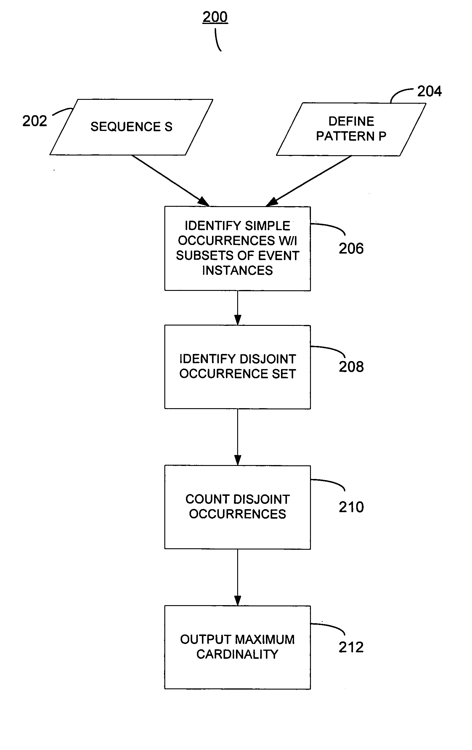
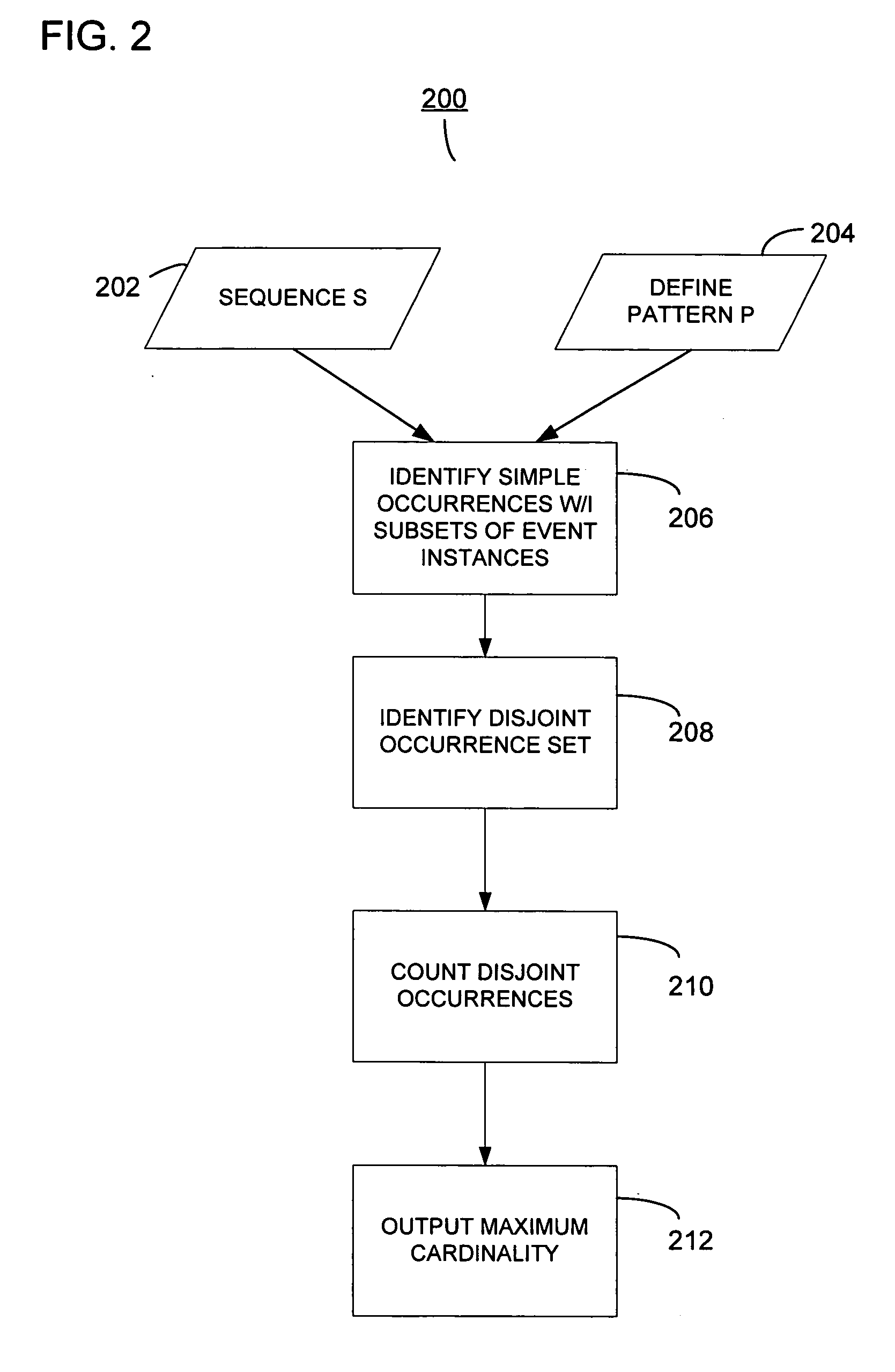
The patent describes a method and system for mining patterns in sequences of time-stamped events. The method involves identifying distinct occurrences of a pattern in the event sequences and determining the maximum cardinality of the pattern. The system includes a computer program that performs these tasks. The technical effects of this invention include improved efficiency and effectiveness in mining patterns, lower data mining costs, and increased opportunity for mining data. Additionally, the system can identify surprising patterns in the event sequences.

Problems solved by technology

While a very large amount of sequential data is stored in databases, generally only a limited amount is analyzed due to the high cost in mining the data.
While events may be ordered in time, their contents have no ordering and are not easily compared to identify a trend or pattern.
Such patterns of events are generally subject to ordering and temporal constraints.
However, this method is limited as the choice of window size is critical.
In addition, the sliding window approach is static and not very robust.
As such, such a method produces an unexpected result due, in part, to the exclusion of some legitimate occurrences.
This method addresses discreet events and their relationship to each other, but does not allow for time overlapping events within the sequence.
As such, this method is not applicable to patterns and sequences containing maintenance events or web transactions that inherently have time overlapped events.
Each of these methods is limited in their application and effectiveness in determining or identifying a pattern within a sequence of time-stamped events or categories.

Method used


Image

  • System and method for analyzing a pattern in a time-stamped event sequence
  • System and method for analyzing a pattern in a time-stamped event sequence
  • System and method for analyzing a pattern in a time-stamped event sequence

Examples


Embodiment Construction

[0038] The following description of the implementations and embodiments is merely exemplary in nature and is in no way intended to limit the invention, its application, or uses. For purposes of clarity, the same reference numbers are used in the drawings to identify similar elements.

[0039] Before describing a system or method for determining the maximum cardinality of a pattern in a sequence, determining the expected maximum cardinality, and identifying a surprising pattern in a sequence, one or more concepts associated with a sequence will be introduced and defined. Thereafter, a detailed description of various embodiments will be described.

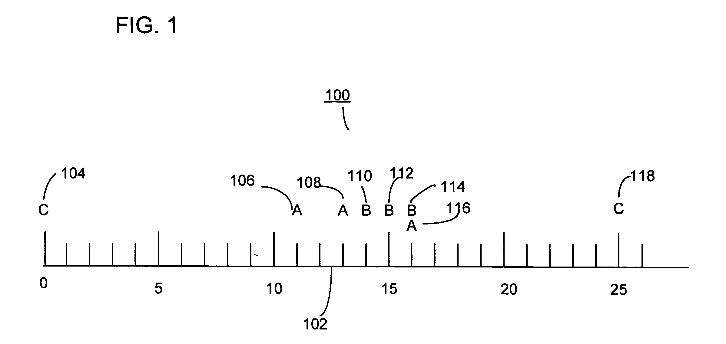
[0040] Following is a list of symbols and terms used throughout this specification. This listing is intended for illustration purposes and is not intended to be limiting. [0041] 1. e—an event instance. [0042] 2. A, B, C, D, and E—Capital Letters are indicative of categories of events. [0043] 3. C(e)—a category of event instance e [0044] 4. b=a...


PUM


Abstract

Preferred embodiments and implementations include a system and method for determining distinct occurrences of a pattern in a sequence of time-stamped event instances by determining a maximum cardinality of disjoint occurrences of the pattern in the one or more sequences. The invention also includes estimating an expected quantity of distinct occurrences of a pattern in a sequence of time-stamped events assigned to event categories. The invention further includes identifying a surprise pattern within a sequence of time-stamped events.

Description

FIELD OF THE INVENTION [0001] The present invention relates to data processing, and more particularly, to the field of data mining of time-stamped events in a temporal sequence and identification of a surprising pattern in the sequence. BACKGROUND OF THE INVENTION [0002] With prevalent application of computer technology to transactions and business operations, a very large amount of operational event data is being generated and stored in databases. In many applications, the stored event data includes a time-stamp that provides for the identification of the time of occurrence of the event. While a very large amount of sequential data is stored in databases, generally only a limited amount is analyzed due to the high cost in mining the data. As such, many patterns of interesting events remain hidden. [0003] It is generally desirable to identify patterns of data events that define relationships between two or more data events. One such method for identifying patterns of data events wit...

Claims


Application Information

Patent Timeline
Patent Type & Authority Applications(United States)
IPC IPC(8): G06F11/00
CPCG06F17/30551G06F16/2477
Inventor WANG, CHANGZHOU
Owner THE BOEING CO
Learn More