Multi-angle adjusting socket body and improved structure of its tools

a multi-angle adjustment and socket technology, applied in the direction of wrenches, screwdrivers, manufacturing tools, etc., can solve the problems of easy detachment, easy fall apart during use, and affect safety, so as to achieve stable and firm operation

Inactive Publication Date: 2005-10-27
CHANG SHENG MING
View PDF0 Cites 34 Cited by
  • Summary
  • Abstract
  • Description
  • Claims
  • Application Information

AI Technical Summary

Benefits of technology

[0006] The present invention comprises a connecting shaft, a locking sleeve for connecting to one end of the connecting shaft, and a tool for connecting to another end of the connecting shaft. The connecting shaft having one end formed as a multi-angular socket for inserting the tool, the inner surface of the multi-angular socket a groove for connecting to the outside, the locking sleeve is sleeved on the multi-angular socket, it comprises an inner bushing, a sliding piece, an elastic piece and a positioning piece. The inner bushing is sleeved on the groove of the connecting shaft, a ball hole is disposed on the inner bushing in corresponding to the groove for placing the positioning piece. The sliding piece is sleeved on the outer end of the connecting shaft, it comprises an outer sleeve and a positioning buckle. The outer sleeve having a stopping part protruded from the inner surface of the outer end, the positioning buckle is buckled on the connecting shaft in corresponding to the stopping part for pressing against the stopping part. When the outer sleeve is connected with the connecting shaft, the elastic piece is disposed between the inner bushing and the stopping part, a stopping edge and a receiving edge of sectional structure are disposed on the inner surface of the elastic piece in neighboring to each other. Another elastic piece is disposed between the other end of the sliding piece and the inner bushing, so that one end of the positioning piece is pressed against by the stopping edge of the sliding piece, and another end is slightly protruded from the groove, so the it is in the way blocking the screw driver inserting path. One end of the tool is connected to a sleeving section of the connecting shaft, another end is formed as a driving part for driving a screw, a turning receiving edge and a plurality of positioning indentations are disposed on the circumference between the sleeving section and the driving part. Accordingly, when the sleeving section of the tool is sleeved inside the multi-angular socket and used in a straight manner, the positioning piece of the locking sleeve is pressed against the positioning indentation to make the operation more stable and firm. When the tool is used in an angular manner, the positioning piece is pressed against the turning receiving edge to make the tool to be able to turn freely.

Problems solved by technology

The connecting method between the connecting shaft and the socket is simply a sleeving method, they are easily to fall apart during usage.
Regardless of the usage of the socket and the connecting shaft is in a straight line or in an angle, or during the procedure when the socket is driven by the wrench, the force is improperly applied on the driven head of the connecting shaft, or the holding angle of the wrench is not properly adjusted, detachment will occur.
The output power is fairly large for electrical or pneumatic tools, if the connecting shaft and the socket fall apart during applying torque, safety will be affected.
Referring to FIG. 4, when using in an angle, even though the steel ball will be fixed on the concave hole of the socket, so that the connection between the connecting shaft and the socket is firmly fixed, nevertheless, the connection is simply in fixed along the circumference, therefore when the socket angle is being adjusted, it will easily shake to make it inconvenient for the user to operate.
Furthermore, the above mentioned connecting shaft having turning function is usually used in socket, and is not suitable for hand tools such as hexagonal screw head.

Method used


Image

  • Multi-angle adjusting socket body and improved structure of its tools
  • Multi-angle adjusting socket body and improved structure of its tools
  • Multi-angle adjusting socket body and improved structure of its tools

Examples


Embodiment Construction

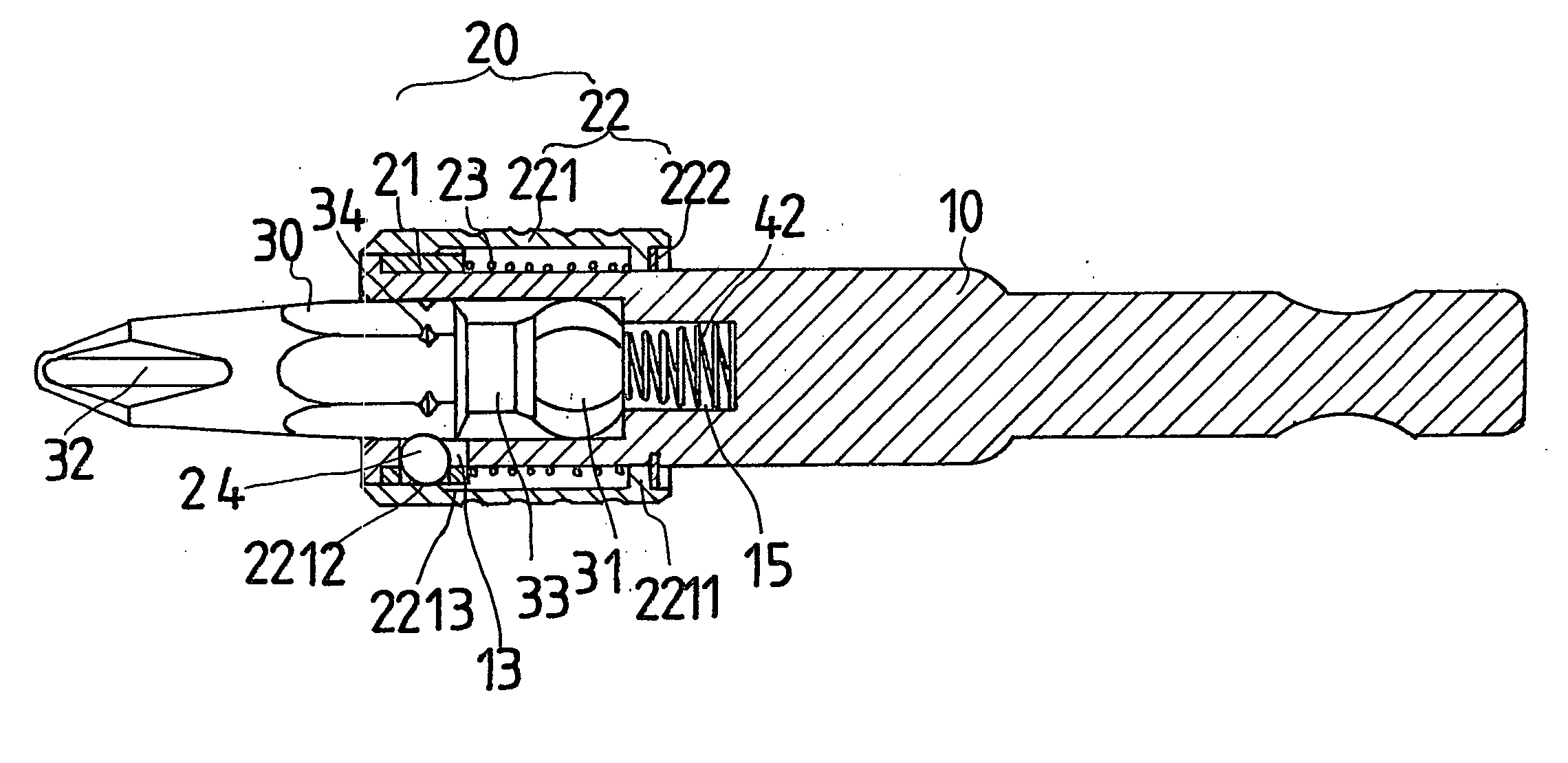
[0018] Referring to FIGS. 5 to 8, the present invention comprises a connecting shaft 10, a locking sleeve 20 for sleeving on one end of the connecting shaft 10, and a tool 30 for connecting to one end of the connecting shaft 10.

[0019] The connecting shaft 10 having a limiting part 11 protruded from one end, and a multi-angular socket 12 for inserting the tool 30. The other end having a connecting section 15 for connecting to power tool such as a wrench or an electrical screwdriver. The multi-angular socket 12 having a groove 13 disposed on the inner surface in corresponding to the tool 30 of multi-angular structure, the locking sleeve 20 is sleeved on it. A ring groove 14 is disposed around the multi-angular socket 12 in corresponding to the locking sleeve 20. The multi-angular socket 12 having a groove hole 15 extended from it and connecting to each other, the groove hole 15 having an elastic spring 42.

[0020] The locking sleeve 20 comprises an inner bushing 21, a sliding piece 22...


PUM


Abstract

A multi-angle adjusting socket body and improved structure of its tools mainly comprises a connecting shaft with one end formed as a multi-angular socket for inserting a tool, a locking sleeve with elasticity and pressing forces for positioning the tool, the tool having one end formed as a sleeving section in ball shape, another end formed as a driving part, a turning concave part and a plurality of indentations are disposed on the circumference of the tool between the sleeving section and the driving part, accordingly, when the sleeving section of the tool is inserted into the multi-angular socket and is used in straight manner, the positioning piece of the locking sleeve presses against on the positioning indentation, so that the operation is performed more stably and firmly, when the tool is used in angular manner, the positioning piece presses against on the turning concave part, thus the tool can be adjusted in different angles.

Description

BACKGROUND OF THE INVENTION [0001] Referring to FIGS. 1 and 2, a “driven tool” such as a ratchet wrench or an electrical tool having a conventional direction—turning connecting shaft (91), its one end having a driven head (92), a concave part (93) is disposed between the connecting shaft (91) and the driven head (92), so that the connecting shaft (91) can turn in a angle. A shoulder (94) is disposed between the concave part (93) and the connecting shaft (91), so that the shoulder (94) can contact the inner surface of a socket (95) to enhance the connection of the socket (95) and the connecting shaft (91) when the driven head (92) is being sleeved with socket (95). [0002] The disadvantages of the conventional are as follows. The connecting method between the connecting shaft and the socket is simply a sleeving method, they are easily to fall apart during usage. Regardless of the usage of the socket and the connecting shaft is in a straight line or in an angle, or during the procedure...

Claims


Application Information

Patent Timeline
Patent Type & Authority Applications(United States)
IPC IPC(8): B25B13/48B25B15/00B25B23/00
CPCB25B13/481B25B15/001B25B23/0035B25B23/0028B25B23/0014
Inventor CHANG, SHENG - MING
Owner CHANG SHENG MING
Why Eureka
Try Eureka