Clamping assembly for limiting the depth of insertion of a respiratory care treatment device

a technology of respiratory care treatment device and assembly, which is applied in the field of clamping assembly, can solve problems such as the depth of insertion of the devi

Active Publication Date: 2005-10-27
AVENT INC
View PDF72 Cites 18 Cited by
  • Summary
  • Abstract
  • Description
  • Claims
  • Application Information

AI Technical Summary

Problems solved by technology

The clamping assembly holds the medical treatment device and limits the depth of insertion of the device into the artificial airway and / or respiratory system of the patient; however, the assembly does allow at least partial retraction of the medical treatment device while the clamp is in use.

Method used


Image

  • Clamping assembly for limiting the depth of insertion of a respiratory care treatment device
  • Clamping assembly for limiting the depth of insertion of a respiratory care treatment device
  • Clamping assembly for limiting the depth of insertion of a respiratory care treatment device

Examples


Embodiment Construction

[0025] Reference will now be made in detail to examples and aspects of the invention. Each example is provided by way of explanation of the invention, and not meant as a limitation of the invention. For example, features illustrated or described as part of one aspect can be used with another aspect to yield a still further aspect. It is intended that the present invention include such modifications and variations not particularly described herein.

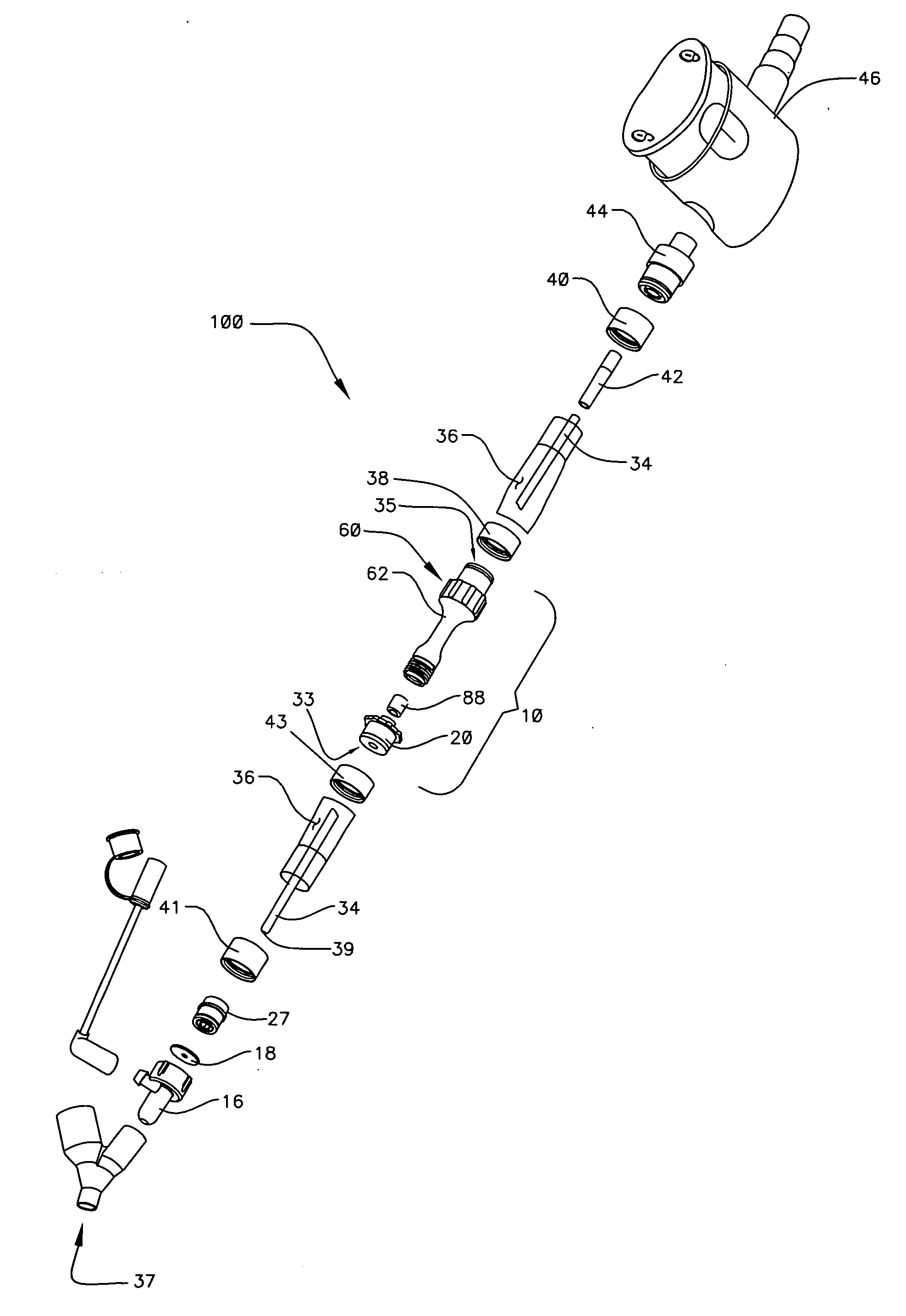
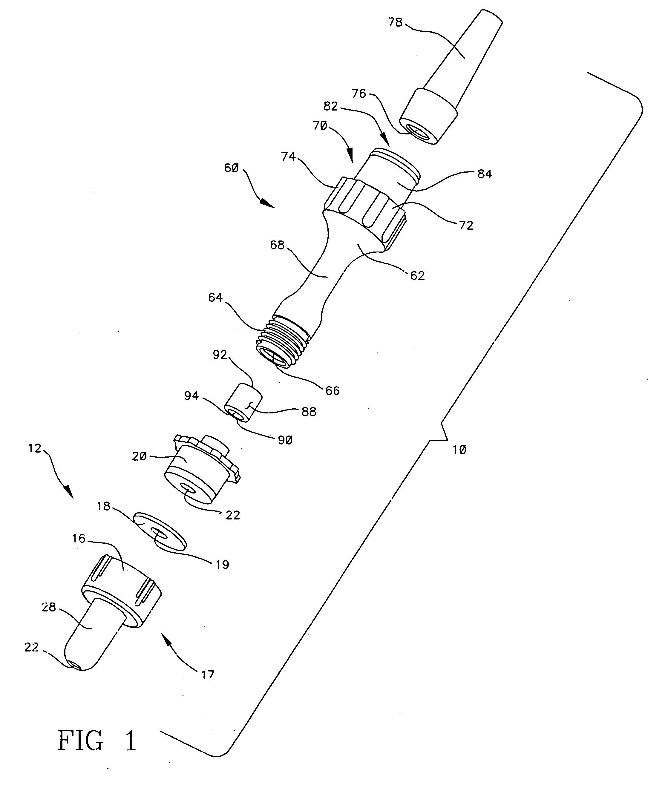
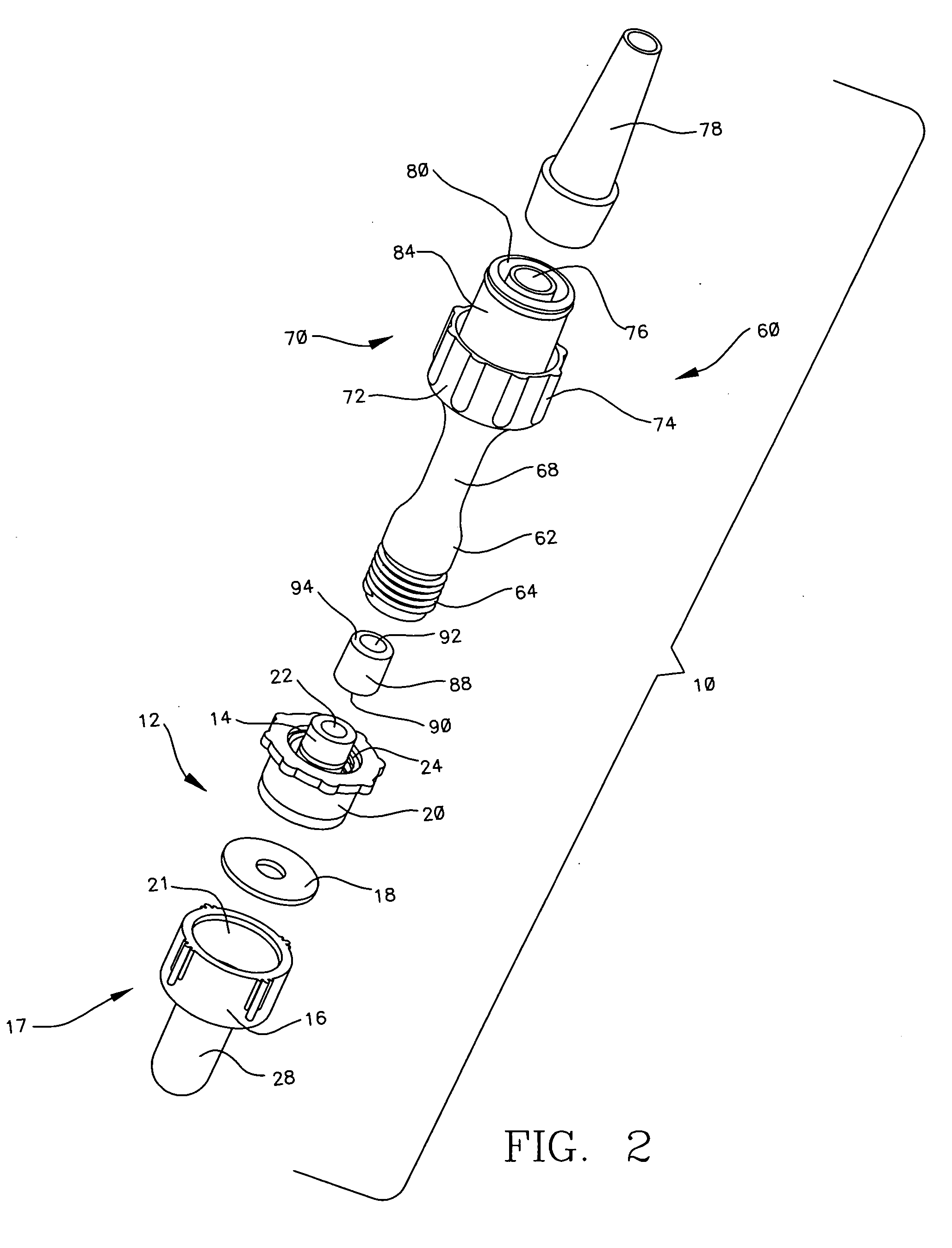
[0026] In the drawings, each aspect is arranged such that the distal direction (referring generally to the direction closer to the patient or the end of the device which is intended to be closer to the patient in use) is located at the bottom of the figure while the proximal direction (generally referring to the direction closer to the clinician or the end of the device which is intended to be closer to the clinician in use) is located at the top of the figure. However, it will be appreciated that in some aspects it may be possible to inve...


PUM


Abstract

A medical device clamping assembly includes proximal and distal axially aligned members. The proximal and distal members are movable relative to each other. A channel is defined through the members for receipt of at least a portion of a treatment device therethrough. A clamping member is configured between the proximal and distal members and defines a portion of the channel. The clamping member is actuated between an unclamped configuration and a clamped configuration by moving one of the distal or proximal members relative to the other. In its clamped position, the clamping member clamps upon and restricts axial movement of the treatment device through the assembly; however, the assembling may move on or within the treatment device and does not necessarily limit at least partial retraction of the device from a patient but rather only restricts insertion of the device beyond that point at which the assembly contacts a stopper.

Description

BACKGROUND [0001] Proper long-term respiratory care of intubated patients requires that multiple medical procedures be performed on the patient. Such procedures may include, for example, ventilation of the patient's lungs; aspiration of secretions from the lungs; oxygenation of the lungs; elimination or reduction of residual CO2from the lungs; visual inspection of portions of the respiratory system; sampling sputum and gases; sensing parameters such as flow rates, pressure, and temperature of gases within the respiratory system; and / or the administration of medication, gases, and / or lavage. [0002] In the majority of these procedures, a medical treatment device, such as a catheter assembly, is connected to a patient's artificial airway, for example a tracheostomy tube or endotracheal tube. A connecting member, such as an adapter, manifold or other like member, may be attached to the proximal end of the artificial airway and the medical treatment device is inserted through the adapter...

Claims


Application Information

Patent Timeline
Patent Type & Authority Applications(United States)
IPC IPC(8): A61M16/04A61M39/06
CPCA61M16/0463A61M2209/06Y10S128/912
Inventor HOOSER, DAVID THERON VANMADSEN, EDWARD B.
Owner AVENT INC
Why Eureka
Try Eureka