Liquid crystal display device and method for producing the same

Active Publication Date: 2005-10-27
SHARP KK
View PDF13 Cites 24 Cited by
  • Summary
  • Abstract
  • Description
  • Claims
  • Application Information

AI Technical Summary

Benefits of technology

[0060] According to the present invention, by using a minute rugged structure which is formed on a surface which is in contact with a liquid crystal layer, a substantially uniform pretilt can be imparted to liquid crystal molecules which are located at a middle level along the thickness direction of the vertical alignment type liquid crystal layer. As a result, the liquid crystal alignment can be controlled with a high precision, whereby high contrast display can be obtained. Since the alignment of the liquid crystal layer can be regulated by a plane (two dimensions), the response characteristics can be improved. Furthermore, alignment division can be realized by controlling the shape and / or arrangement of the rugged structure, the viewing angle characteristics can be improved.

Problems solved by technology

However, in the case of a vertical alignment type liquid crystal display device, the pretilt direction of the liquid crystal layer cannot be stably controlled even by performing a rubbing treatment for the vertical alignment films which are provided for the sake of alignment control.
Moreover, since a vertical alignment type liquid crystal display device has a higher contrast than that of the horizontal alignment type liquid crystal display device, even a slight non-uniformity in alignment can be visually recognized, thus resulting in display unevenness.
Since cloth is to be used for rubbing, the division precision would become poor, thus making practical applications difficult.
On the other hand, the rib technique and the fringe field technique also have a problem in that, since ribs or slits are provided within each pixel, the aperture ratio decreases, thus resulting in a dark display.
Furthermore, the structures of the substrates, electrodes, and like elements may become complicated, so that the productivity may be lowered and the production cost may increase with increase in the number of steps involved in the production process.
However, these methods have the following problems because oblique evaporation is utilized for producing such a structure.
Firstly, it is difficult with oblique evaporation to control the surface configuration of a structure to a high precision.
This problem is particularly outstanding in the case where unit features are to be formed on a vertical alignment film surface with a small pitch of, e.g., several μm or less.
Secondly, it is impossible to arbitrarily prescribe the configuration of each unit feature of the structure (i.e., angle, orientation, etc., of the slanted faces of the grooves).
Therefore, it is difficult to obtain a pretilt with an arbitrary direction or angle, and thus, there are limitations on the applications of the display device.
Using oblique evaporation to produce a structure for forming such a vertical alignment film, however, would complicate the production process.
Thus, pompous equipment is required, thus making the production of large-sized display devices difficult.
However, KAWAI et al. lack any mention of causing a pretilt of vertically aligned liquid crystal molecules.
Moreover, the ruggednesses which are described KAWAI et al. are obtained by allowing perpendicularly-intersecting sinusoidal interference fringes to exist, and therefore, there are limitations on the configuration and arrangement of the fine grooves that can be selected.
Furthermore, since similar features are formed along two directions perpendicular to each other (x direction, y direction), it is difficult to separately control the features along the x direction from the features along the y direction.
Therefore, when this method is applied to a display device of MVA mode, for example, the production process may be complicated.
As described above, although there have been proposed methods for providing minute undulations (ruggednesses) on a surface which is in contact with a liquid crystal layer in order to perform alignment control of a vertical alignment type liquid crystal layer, it is difficult to obtain arbitrary and strict control of liquid crystal alignment without lowering the aperture ratio or complicating the production process.

Method used


Image

  • Liquid crystal display device and method for producing the same
  • Liquid crystal display device and method for producing the same
  • Liquid crystal display device and method for producing the same

Examples


embodiment 1

[0153] Hereinafter, the structure of a liquid crystal display device according to Embodiment 1 of the present invention will be described with reference to the accompanying drawings.

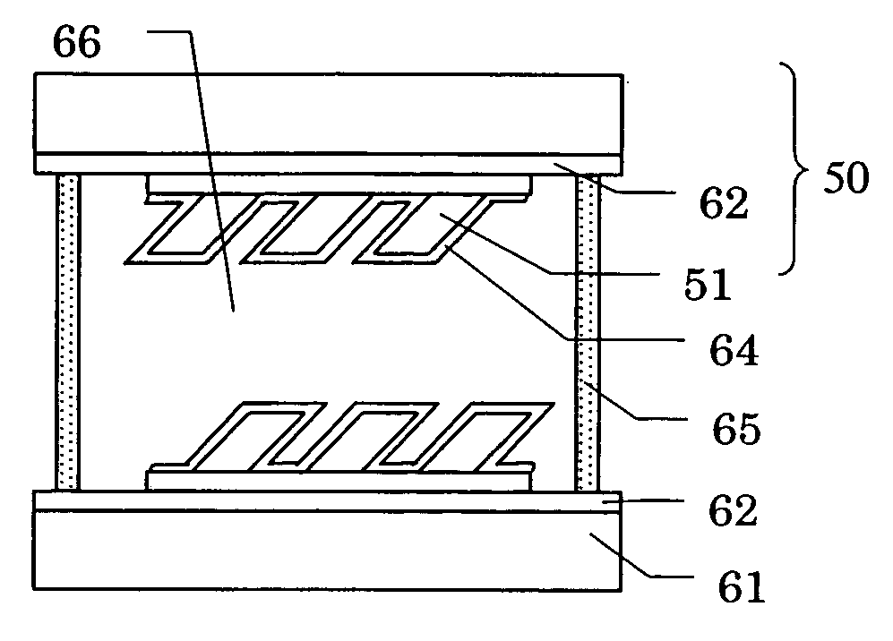
[0154]FIGS. 11A and 11B are schematic cross-sectional views illustrating exemplary structures of the liquid crystal display device of the present embodiment. The liquid crystal display device shown in FIG. 11A includes a pair of alignment controlling elements 50 attached together via spacers (thickness: 5 μm) 65, and a liquid crystal layer 66 interposed therebetween. The alignment controlling element 50 includes a glass substrate 61 and an electrode 62 formed on the glass substrate 61, with an alignment controlling structure being formed on the electrode 62. The alignment controlling structure includes an arrangement of a plurality of unit features 51. The unit features 51 are formed of, for example, a resin material. Each unit feature 51 has an asymmetric quadrangular cross section. In the alignment co...

embodiment 2

[0207] Hereinafter, a liquid crystal display device according to Embodiment 2 of the present invention will be described with reference to the accompanying drawings. The liquid crystal display device of the present embodiment has a similar structure to that of Embodiment 1 as described with reference to FIGS. 11A and 11B, except for the following difference.

[0208] The alignment controlling element employed in Embodiment 1 includes a plurality of unit features each having an asymmetric cross-sectional shape. Therefore, in Embodiment 1, disclinations are caused by confining liquid crystal alignment within certain regions or spaces, by utilizing ruggednesses consisting of unit features. On the other hand, the alignment controlling element of the present embodiment includes a plurality of columnar unit features each having side walls which are perpendicular to the substrate surface. By using such an alignment controlling element, as has been described above with reference to FIGS. 8C a...

embodiment 3

[0225] Hereinafter, a liquid crystal display device according to Embodiment 3 of the present invention will be described. The liquid crystal display device of the present embodiment has a similar structure to that of Embodiment 1 as described with reference to FIGS. 11A and 11B, except that the device of the present embodiment is an MVA mode liquid crystal display device employing an alignment controlling element which is divided into regions.

[0226] As described earlier, in order to improve the viewing angle in VAN mode, it is preferable that different pretilt directions exist within each pixel (MVA mode). According to the present invention, a pretilt direction can be arbitrarily set based on the ruggednesses on a surface which is in contact with the liquid crystal layer, and therefore MVA mode is relatively easy to realize.

[0227] An exemplary structure of the alignment controlling element of the present embodiment will be described with reference to FIGS. 17 and 18.

[0228] As sho...


PUM

PropertyMeasurementUnit
Lengthaaaaaaaaaa
Lengthaaaaaaaaaa
Angleaaaaaaaaaa

Abstract

A liquid crystal display device 700 includes a pair of substrates, a vertical alignment type liquid crystal layer 490 provided between the pair of substrates, and electrodes 481 and 485 for applying a voltage to the vertical alignment type liquid crystal layer 490. At least one of the pair of substrates has a rugged structure on a surface which is in contact with the vertical alignment type liquid crystal layer. The surface having the rugged structure formed thereon has a region in which the height of the rugged structure varies along a first direction with a first period and varies along a second direction perpendicular to the first direction with a second period different from the first period. The first period is no less than 0.1 μm and no more than 10 μm, and the second period is no less than 0.1 μm and no more than 10 μm. The vertical alignment type liquid crystal layer 490 has a pretilt due to the rugged structure with no voltage applied thereacross.

Description

BACKGROUND OF THE INVENTION [0001] 1. Field of the Invention [0002] The present invention relates to a liquid crystal display device and a method for producing the same. [0003] 2. Description of the Related Art [0004] Liquid crystal display devices (LCD) are in wide use as display devices for computers or television sets. So far, horizontal alignment type LCDs have been prevalent. A horizontal alignment type LCD operates in a liquid crystal display mode such as TN (Twisted Nematic) mode or STN (Super Twisted Nematic) mode using a positive nematic liquid crystal. [0005] Recently, in order to provide improved viewing angle characteristics and display contrast, vertical alignment type LCDs using VAN (Vertical Aligned Nematic) mode have come into practical use. A vertical alignment type LCD is an LCD which performs display in a normally black (NB) mode by employing a vertical alignment type liquid crystal layer provided between a pair of electrodes. [0006] In order to enhance the displa...

Claims


Application Information

Patent Timeline
IPC IPC(8): B29C59/04G02F1/133G02F1/1333G02F1/1337G02F1/139
CPCB29C59/046B82Y20/00G02F1/133753G02F1/13378G02F2202/36G02F2001/133757G02F2001/133761G02F2001/133776G02F2001/133792G02F1/1393G02F1/133757G02F1/133761G02F1/133776G02F1/133792E04H17/04E04H17/06
Inventor KAWAMURA, TADASHI
Owner SHARP KK
Why Eureka
Try Eureka