Antirotational structures for wave energy converters

a technology of anti-rotational structure and wave energy, which is applied in the direction of enzymology, machine/engine, electric generator control, etc., can solve the problems of potentially damaging twisting or rotational motion, high undesirable, and add to the complexity and cost of design, so as to facilitate the use of pto, improve the efficiency of operation, and improve the effect of electromagnetic coupling

Active Publication Date: 2005-10-27
OCEAN POWER TECHNOLOGIES
View PDF6 Cites 40 Cited by
  • Summary
  • Abstract
  • Description
  • Claims
  • Application Information

AI Technical Summary

Benefits of technology

[0009] A significant aspect of the inventive structure is that it facilitates the use of a PTO which includes a linear electric generator (LEG) system designed to produce electrical energy, directly, in response to the relative motion between the shell and the column. The LEG system includes a permanent magnetic assembly (PMA) and an induction coil assembly (ICA) which perform better when formed between and along parallel surfaces whose dimensions and spacing can be maintained relatively constant. This feature aids to maintain good and efficient electromagnetic coupling of the components (PMA and ICA) of the LEG, ensuring more efficient operation.
[0010] Typically, in WECs including anti-rotational structures, one of the PMA and ICA is located on, or in, or attached to, the shell and moves as the shell moves; and the other one of the PMA and ICA is located on, or attached to, the column and either moves as the column moves or remains stationary if the column is stationary. Relative motion between the shell and column, when placed in a body of water and in response to waves in the body of water, causes the attached (or mounted) PMA and ICA assemblies to be driven, vertically, past each other, in response to motion of the waves, resulting in the generation of output voltages which are a function of the relative vertical motion while preventing rotational and twisting motion.
[0011] The parallel surfaces provided by the shell's inner walls and the column's outer wall facilitate the incorporation of a guide and bearing system which maintains the relative alignment of the magnetic and induction coil assemblies and the spacing between them.

Problems solved by technology

The twisting or rotational motion is potentially damaging and is highly undesirable.
Incorporating such restraining members adds to the complexity and cost of the design and still allows for some twisting along the column, if the anti-rotation mechanism is only introduced at one end of the column.

Method used


Image

  • Antirotational structures for wave energy converters
  • Antirotational structures for wave energy converters
  • Antirotational structures for wave energy converters

Examples


Embodiment Construction

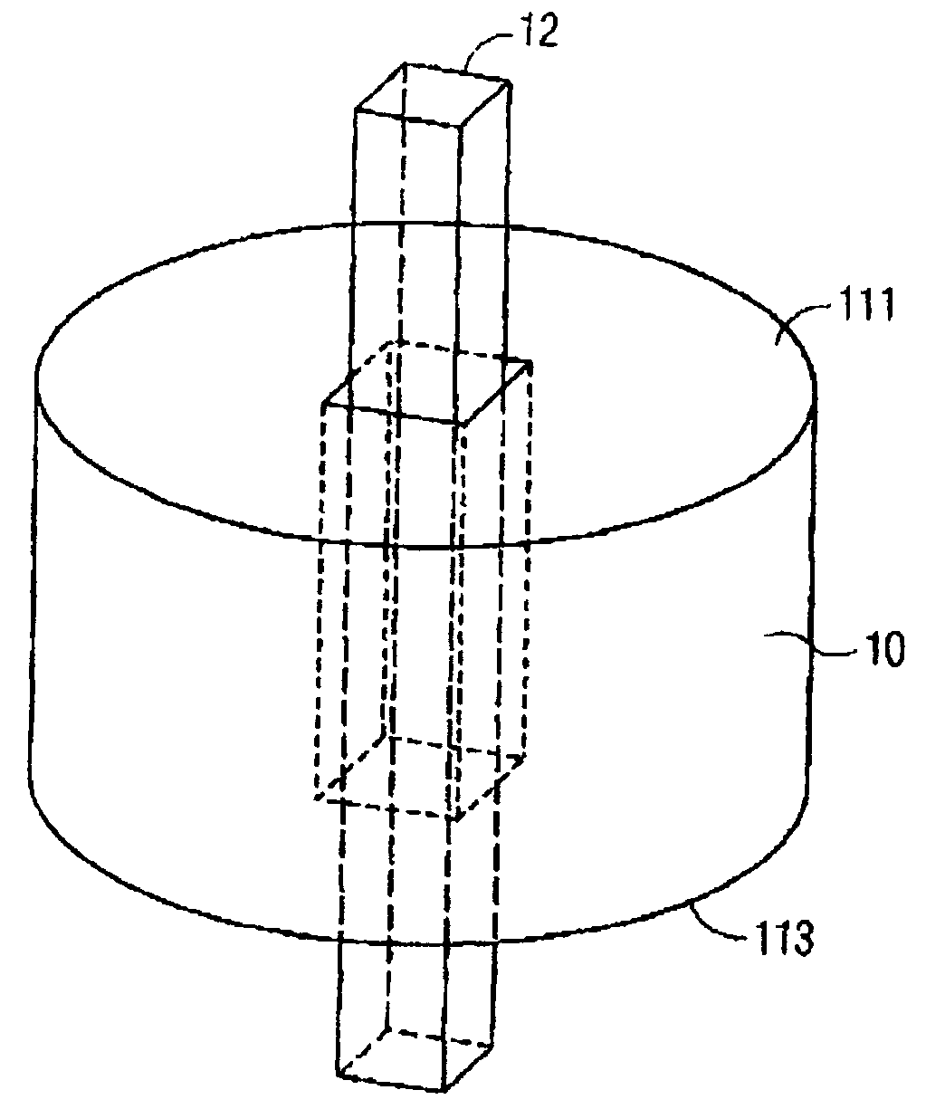
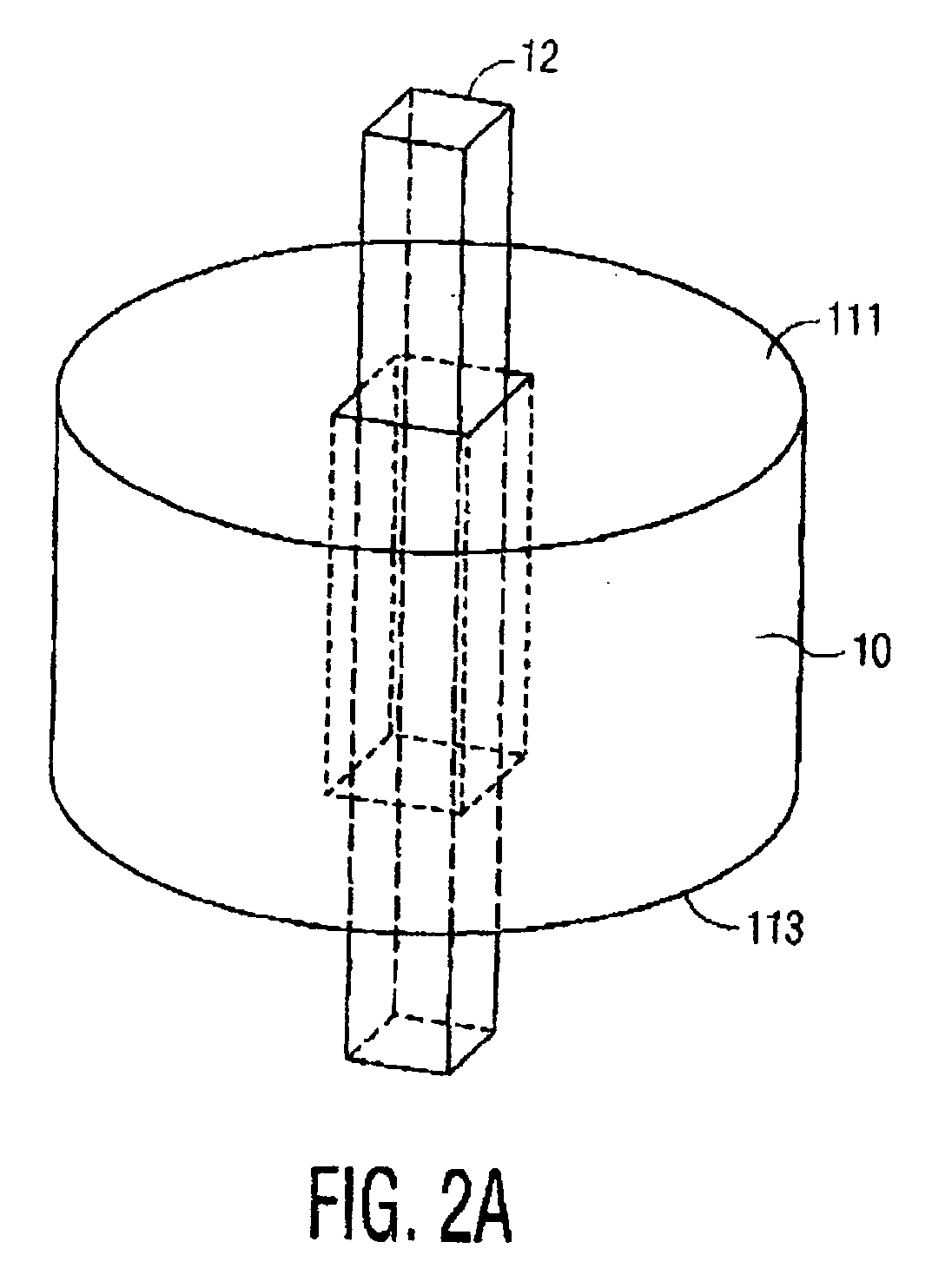
[0025] Referring to FIG. 2A there is shown a square elongated column 12 extending above the top 111 of a shell 10 and below the bottom 113 of the shell. The shell 10 has a central opening shaped to correspond in a complementary manner to the walls of the column to enable the column 12 to fit through the central opening of the shell 10, whereby the shell and column can move vertically, up and down, relative to each other, while preventing any rotational motion. As shown in FIGS. 2A and 2B, the sides of the column (12a, 12b, 12c, 12d) define plane surfaces extending along the column. Corresponding to each side (12a, 12b, 12c, 12d) of the column is a side (103a, 103b, 103c, 103d) of the inner wall of the shell, each inner shell side defining a plane surface which is generally parallel to the corresponding side or face of the column. This structure enables the shell and column to slide past each other while allowing virtually no rotational movement between the shell and column.

[0026]FI...


PUM

PropertyMeasurementUnit
wave energyaaaaaaaaaa
electrical energyaaaaaaaaaa
electric energyaaaaaaaaaa

Abstract

A WEC embodying the invention includes a non-circular main central column positioned within a like non-circular central opening of a shell to contain the central column and prevent rotation or twisting of the shell relative to the column. In a particular embodiment, the central column is multi-sided (e.g., a square) and the central opening of the shell is likewise multi-sided (e.g., square). The facing sides of the column and shell are parallel to each other facilitating the layout of the components of a linear electric generator (LEG) between the facing sides and ensuring good magnetic coupling between the components of the LEG over the length of travel of the shell and column.

Description

CROSS REFERENCES TO RELATED APPLICATIONS [0001] This application claims priority from provisional patent application Ser. No. 60 / 553,666 titled Wave Energy Converters (WECs) with Linear Electric Generators (LEGs) filed Mar. 16, 2004, the teachings of which are incorporated herein by reference.BACKGROUND OF THE INVENTION [0002] This invention relates to apparatus, systems and methods for converting energy present in ocean surface waves into electric energy. [0003] Known wave energy converter (WEC) systems for capturing ocean surface wave energy include: (a) a first component (also referred to herein as a “shell” or “vessel” or “float”) which, when placed in a body of water, is designed to move up and down, generally, in phase with the waves in the water and thus absorb and / or release energy; (b) a second component (also referred to herein as a “shaft”, “spar”, “column” or piston) which is either stationary or moves generally out of phase relative to the waves and the first structure;...

Claims


Application Information

Patent Timeline
Patent Type & Authority Applications(United States)
IPC IPC(8): A01D75/30C12N9/42F03B13/18F03B13/20F03B15/00F03C1/00H02K7/18H02K35/02
CPCB60L7/003H02P25/18F03B13/20F05B2220/7068F05B2220/707F05B2260/50F05B2260/903H02K7/1876H02K35/02H02P3/22Y02E10/38Y02T10/641Y02T10/642H02P9/008F03B13/1845Y02P60/12H02K35/04H02K7/106Y02E10/30Y02T10/64
Inventor SABOL, THOMASSTEWART, DAVID B.
Owner OCEAN POWER TECHNOLOGIES
Why Eureka
Try Eureka