Transmission device

Inactive Publication Date: 2005-10-27
FUJITSU LTD
View PDF9 Cites 24 Cited by
  • Summary
  • Abstract
  • Description
  • Claims
  • Application Information

AI Technical Summary

Problems solved by technology

However, the conventional transmission device has the problem that a fault in communication from the Root Port, Alternate Port or Backup Port to the Designated Port cannot be detected.

Method used


Image

  • Transmission device
  • Transmission device
  • Transmission device

Examples


Embodiment Construction

[0051] The principles of the present invention will be hereinafter described in detail with reference to the drawings.

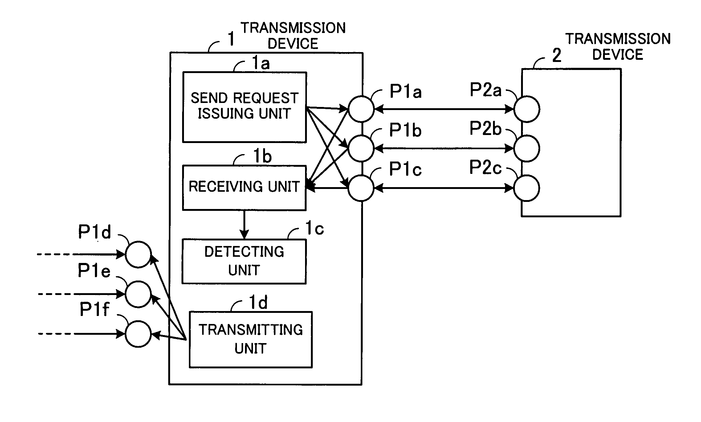
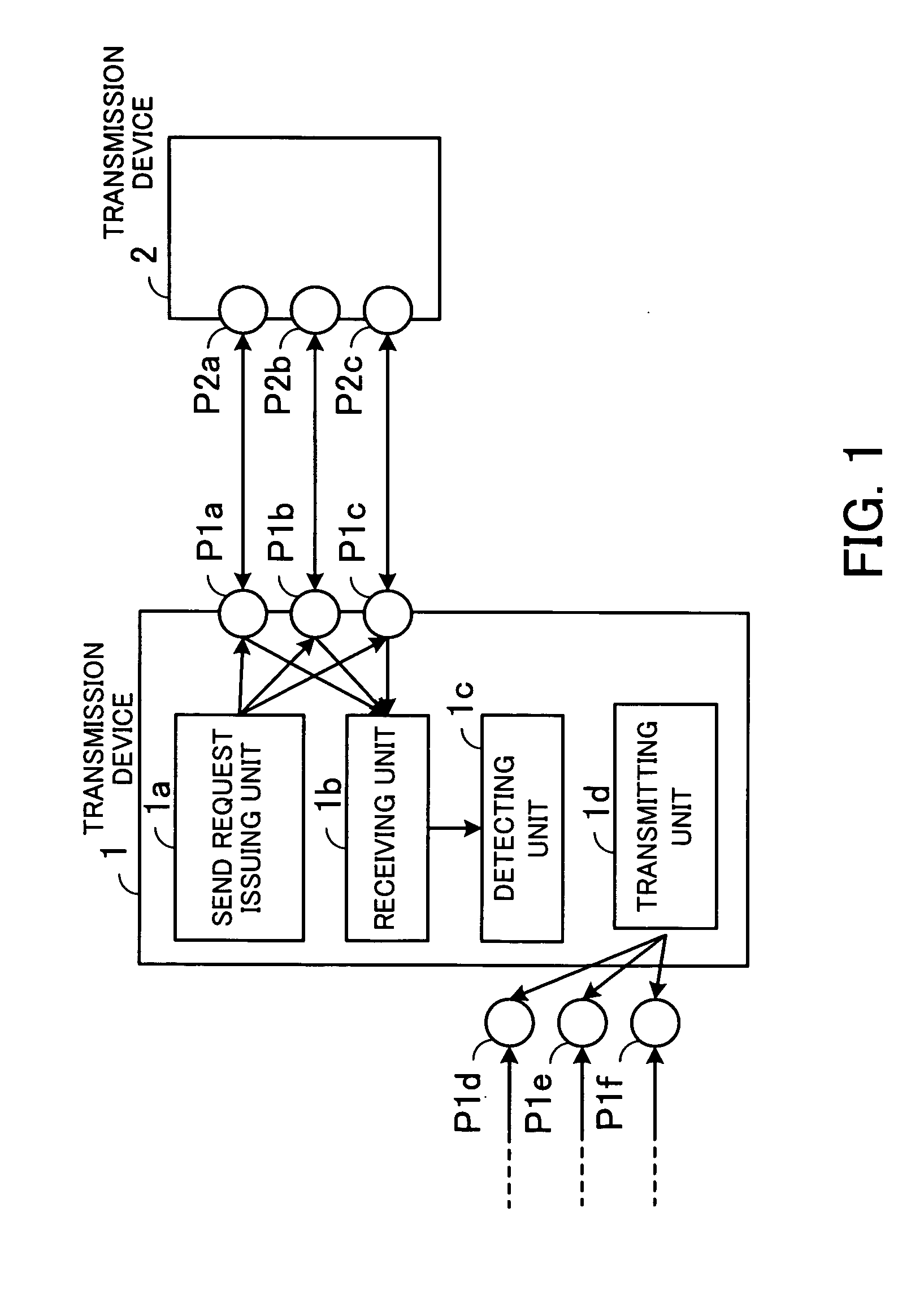
[0052]FIG. 1 illustrates the principle of a transmission device according to the present invention.

[0053] As shown in the figure, the transmission device 1 comprises send request issuing unit 1a, receiving unit 1b, detecting unit 1c, and transmitting unit 1d.

[0054] If the transmission device 1 has Designated Ports P1a, P1b and P1c because of execution of the Spanning Tree Protocol, the send request issuing unit 1a issues a send request from the Designated Ports P1a, P1b and P1c to a transmission device 2 to request same to transmit fault monitoring data.

[0055] The receiving unit 1b receives the fault monitoring data from a Root Port P2a, Alternate Port P2b and Backup Port P2c of the transmission device 2 with respect to which the send request was issued.

[0056] The detecting unit 1c detects a communication fault on the basis of reception of the fault monitoring d...


PUM


Abstract

A transmission device capable of detecting a fault in communication from any of a root port, alternate port and backup port to a designated port. When the transmission device has designated ports, send request issuing unit thereof issues a send request from the designated ports to an associated transmission device to request same to transmit fault monitoring data. Receiving unit receives fault monitoring data from a root port, alternate port and backup port of the associated transmission device, and detecting unit detects a communication fault based on reception of the fault monitoring data. When the transmission device has a root port, an alternate port and a backup port, transmitting unit thereof transmits fault monitoring data from the root port, the alternate port and the backup port in response to a send request from an associated transmission device.

Description

CROSS-REFERENCE TO RELATED APPLICATIONS [0001] This application is based upon and claims priority of Japanese Patent Application No. 2004-131507, filed on Apr. 27, 2004, the contents being incorporated herein by reference. BACKGROUND OF THE INVENTION [0002] (1) Field of the Invention [0003] The present invention relates to a transmission device, and more particularly, to a transmission device for controlling routing by means of a spanning tree protocol. [0004] (2) Description of the Related Art [0005] Spanning Tree Protocol (hereinafter STP) is a protocol defined in the IEEE 802.1D standard (Media Access Control (MAC) Bridges) and used to configure a single spanning tree (loop-free tree) in a desired bridged LAN (Local Area Network) topology (see, for example, Japanese Unexamined Patent Publication No. 2003-115855 (paragraph nos. [0017] to [0023], FIG. 1) and Japanese Unexamined Patent Publication No. H08-32611 (paragraph nos. [0056] to [0058], FIG. 1)). STP has now been expanded in...

Claims


Application Information

Patent Timeline
IPC IPC(8): H04L12/44H04L12/46H04L69/40
CPCH04L12/462H04L41/06H04L45/28H04L45/22H04L41/0604
Inventor SASAGAWA, YASUSHI
Owner FUJITSU LTD
Why Eureka
Try Eureka