Method and apparatus for high rate packet data transmission

a packet data and high-rate technology, applied in data switching networks, data communication services, power management, etc., can solve the problems of imposing stringent and fixed delay requirements, unable to support unable to achieve reliable communication at a rate greater than 122.88 kbps, so as to improve the efficiency of a cdma system and high-rate packets

Inactive Publication Date: 2006-07-18
QUALCOMM INC
View PDF35 Cites 91 Cited by
  • Summary
  • Abstract
  • Description
  • Claims
  • Application Information

AI Technical Summary

Benefits of technology

[0018]The present invention is a novel and improved method and apparatus for high rate packet data transmission in a CDMA system. The present invention improves the efficiency of a CDMA system by providing for means for transmitting data on the forward and reverse links. Each mobile station communicates with one or more base stations and monitors the control channels for the duration of the communication with the base stations. The control channels can be used by the base stations to transmit small amounts of data, paging messages addressed to a specific mobile station, and broadcast messages to all mobile stations. The paging message informs the mobile station that the base station has a large amount of data to transmit to the mobile station.
[0019]It is an object of the present invention to improve utilization of the forward and reverse link capacity in the data communication system. Upon receipt of the paging messages from one or more base stations, the mobile station measures the signal-to-noise-and-interference ratio (C / I) of the forward link signals (e.g. the forward link pilot signals) at every time slots and selects the best base station using a set of parameters which can comprise the present and previous C / I measurements. In the exemplary embodiment, at every time slot, the mobile station transmits to the selected base station on a dedicated data request (DRC) channel a request for transmission at the highest data rate which the measured C / I can reliably support. The selected base station transmits data, in data packets, at a data rate not exceeding the data rate received from the mobile station on the DRC channel. By transmitting from the best base station at every time slot, improved throughput and transmission delay are achieved.
[0020]It is another object of the present invention to improve performance by transmitting from the selected base station at the peak transmit power for the duration of one or more time slots to a mobile station at the data rate requested by the mobile station. In the exemplary CDMA communication system, the base stations operate at a predetermined back-off (e.g., 3 dB) from the available transmit power to account for variations in usage. Thus, the average transmit power is half of the peak power. However, in the present invention, since high speed data transmissions are scheduled and power is typically not shared (e.g., among transmissions), it is not necessary to back-off from the available peak transmit power.
[0021]It is yet another object of the present invention to enhance efficiency by allowing the base stations to transmit data packets to each mobile station for a variable number of time slots. The ability to transmit from different base stations from time slot to time slot allows the data communication system of the present invention to quickly adapt to changes in the operating environment. In addition, the ability to transmit a data packet over non-contiguous time slots is possible in the present invention because of the use of sequence number to identify the data units within a data packet.
[0022]It is yet another object of the present invention to increase flexibility by forwarding the data packets addressed to a specific mobile station from a central controller to all base stations which are members of the active set of the mobile station. In the present invention, data transmission can occur from any base station in the active set of the mobile station at each time slot. Since each base station comprises a queue which contains the data to be transmitted to the mobile station, efficient forward link transmission can occur with minimal processing delay.

Problems solved by technology

A significant difference between voice services and data services is the fact that the former imposes stringent and fixed delay requirements.
Furthermore, the path loss is subject to random variations due to man-made or natural obstructions within the path of the radio wave.
On the other hand, if a mobile station is subject to substantial interference from adjacent base stations and can only achieve a C / I of −7 dB, reliable communication cannot be supported at a rate greater than 122.88 Kbps.

Method used


Image

  • Method and apparatus for high rate packet data transmission
  • Method and apparatus for high rate packet data transmission
  • Method and apparatus for high rate packet data transmission

Examples


first embodiment

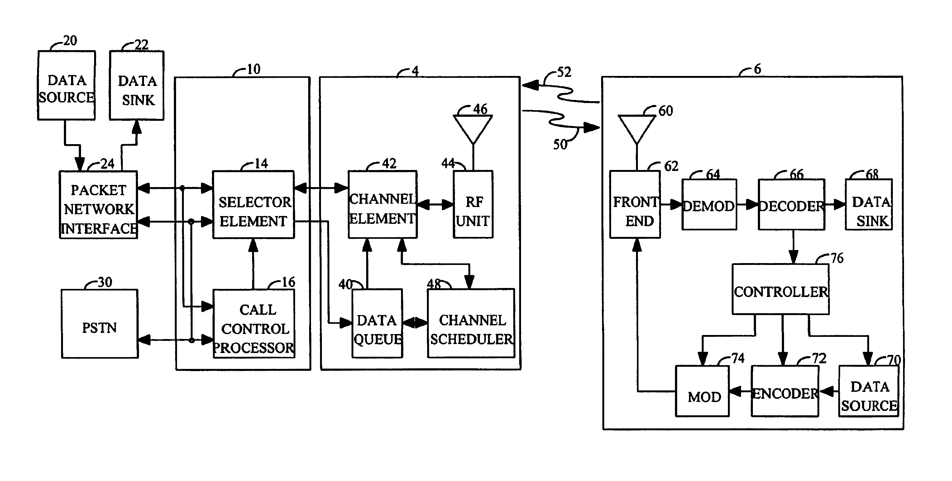
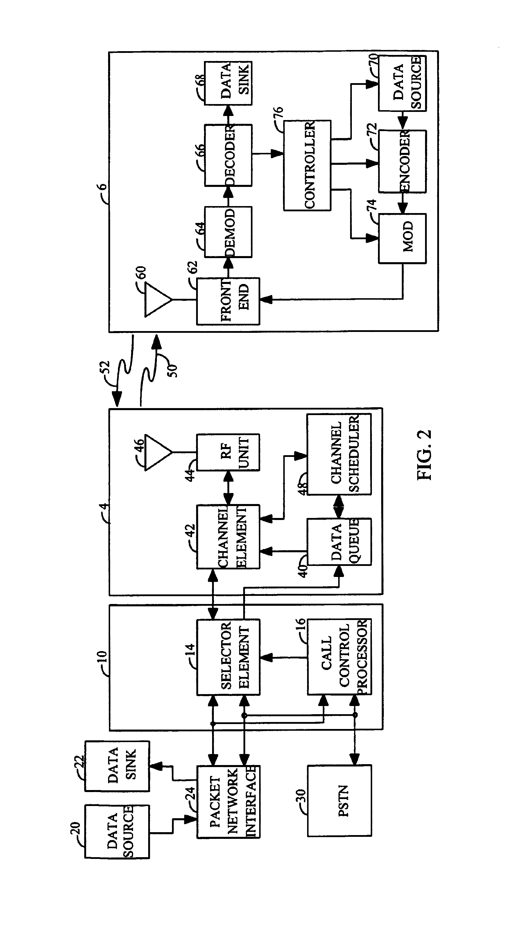
[0072]In the first embodiment, base station 4 transmits at the requested data rate. This embodiment confers to mobile station 6 the important decision of selecting the data rate. Always transmitting at the requested data rate has the advantage that mobile station 6 knows which data rate to expect. Thus, mobile station 6 only demodulates and decodes the traffic channel in accordance with the requested data rate. Base station 4 does not have to transmit a message to mobile station 6 indicating which data rate is being used by base station 4.

[0073]In the first embodiment, after reception of the paging message, mobile station 6 continuously attempts to demodulate the data at the requested data rate. Mobile station 6 demodulates the forward traffic channel and provides the soft decision symbols to the decoder. The decoder decodes the symbols and performs the frame check on the decoded packet to determine whether the packet was received correctly. If the packet was received in error or if...

second embodiment

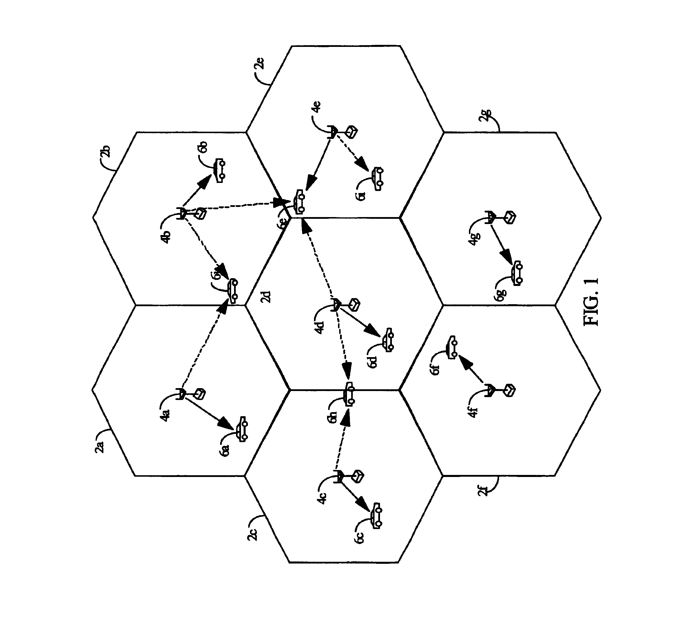
[0087]In the second embodiment, each base station 4 transmits a forward activity bit (hereinafter referred to as the FAC bit) which indicates whether a transmission will occur at the next half frame. The use of the FAC bit is described in detail below. Mobile station 6 performs the C / I measurement taking into account the received FAC bit from each base station 4.

third embodiment

[0088]In the third embodiment, which corresponds to the scheme wherein an indication of the link quality is transmitted to base station 4 and which uses a centralized scheduling scheme, the scheduling information indicating which ones of base stations 4 transmitted data at each time slot is made available to channel scheduler 48. Channel scheduler 48 receives the C / I measurements from mobile stations 6 and can adjust the C / I measurements based on its knowledge of the presence or absence of data transmission from each base station 4 in the data communication system. For example, mobile station 6 can measure the C / I at the first time slot when no adjacent base stations 4 are transmitting. The measured C / I is provided to channel scheduler 48. Channel scheduler 48 knows that no adjacent base stations 4 transmitted data in the first time slot since none was scheduled by channel scheduler 48. In scheduling data transmission at the second time slot, channel scheduler 48 knows whether one o...


PUM


Abstract

In a data communication system capable of variable rate transmission, high rate packet data transmission improves utilization of the forward link and decreases the transmission delay. Data transmission on the forward link is time multiplexed and the base station transmits at the highest data rate supported by the forward link at each time slot to one mobile station. The data rate is determined by the largest C / I measurement of the forward link signals as measured at the mobile station. Upon determination of a data packet received in error, the mobile station transmits a NACK message back to the base station. The NACK message results in retransmission of the data packet received in error. The data packets can be transmitted out of sequence by the use of sequence number to identify each data unit within the data packets.

Description

CLAIM OF PRIORITY UNDER 35 U.S.C. §120[0001]The present Application for Patent is a Continuation and claims priority to patent application Ser. No. 08 / 963,386 entitled “METHOD AND APPARATUS FOR HIGH RATE PACKET DATA TRANSMISSION” filed Nov. 3, 1997, now U.S. Pat. No. 6,574,211, issued Jun. 3, 2003, and assigned to the assignee hereof and hereby expressly incorporated by reference herein.BACKGROUND OF THE INVENTION[0002]I. Field of the Invention[0003]The present invention relates to data communication. More particularly, the present invention relates to a novel and improved method and apparatus for high rate packet data transmission.[0004]II. Description of the Related Art[0005]A modern day communication system is required to support a variety of applications. One such communication system is a code division multiple access (CDMA) system which conforms to the “TIA / EIA / IS-95 Mobile Station-Base Station Compatibility Standard for Dual-Mode Wideband Spread Spectrum Cellular System”, her...

Claims


Application Information

Patent Timeline
Patent Type & Authority Patents(United States)
IPC IPC(8): H04J3/22H04B1/7103H04W40/16H04B7/005H04L1/00H04L1/08H04L1/16H04L1/18H04L12/56H04L29/08H04W16/14H04W24/00H04W28/22H04W52/04H04W52/12H04W52/24H04W52/26H04W52/40H04W72/08
CPCH04B1/7103H04W28/22H04W52/04H04B2201/70702H04B2201/709709H04L1/08H04L1/1628H04W16/14H04W52/40H04W52/12H04W52/241H04W52/248H04W52/26H04W24/00H04W28/18H04L1/00
Inventor PADOVANI, ROBERTOBENDER, PAUL E.BLACK, PETER J.GROB, MATTHEW S.HINDERLING, JURG K.SINDHUSHAYANA, NAGABHUSHANA T.WHEATLEY, III, CHARLES E.
Owner QUALCOMM INC
Why Eureka
Try Eureka