
Methods, apparatuses and systems facilitating data transmission across bonded communications paths

a technology of bonded communication paths and methods, applied in data switching networks, high-level techniques, multiplex communication, etc., can solve the problems of limiting the allowable difference in link speed between bonded links, requiring the use of expensive optical fiber and optical network equipment, and unattractive ds3 links for many enterprise customers, so as to efficiently utilize the available link capacity and fluidly handle the difference in link speed

Inactive Publication Date: 2006-02-28
KLAMATH NETWORKS
View PDF3 Cites 98 Cited by
  • Summary
  • Abstract
  • Description
  • Claims
  • Application Information

AI Technical Summary

Benefits of technology

This approach enables the efficient aggregation of physical links into higher-bandwidth logical links, effectively utilizing available link capacity and ensuring desired QoS levels, even over links with varying speeds, thus providing a cost-effective and high-bandwidth solution for telecommunications.

Problems solved by technology

DS3 links, however, are unattractive to many enterprise customers since electrical DS3 solutions are capable of supporting access links of only about 900 feet in length, therefore mandating use of expensive optical fiber and optical network equipment for any access link spanning a significant distance.
For IMA, the third requirement ends up being the most taxing on the solution, because an ATM cell is a fixed size packet, and therefore does not allow for the simple addition of a sequence number to every cell to allow for re-sequencing of the data stream at the receiving end.
These conditions limit the allowable difference in link speed among the bonded links.
However, the minimal allowable link speed difference supported by IMA is a substantial obstacle against such an implementation.
Even assuming this obstacle can be overcome, IMA still suffers from the inefficiencies introduced by the cell-stuffing events that bring the effective user bandwidth capacity of all links down to the lowest common denominator.

Method used


Image

  • Methods, apparatuses and systems facilitating data transmission across bonded communications paths
  • Methods, apparatuses and systems facilitating data transmission across bonded communications paths
  • Methods, apparatuses and systems facilitating data transmission across bonded communications paths

Examples


Embodiment Construction

I. Operating Environment

A. Functional Overview

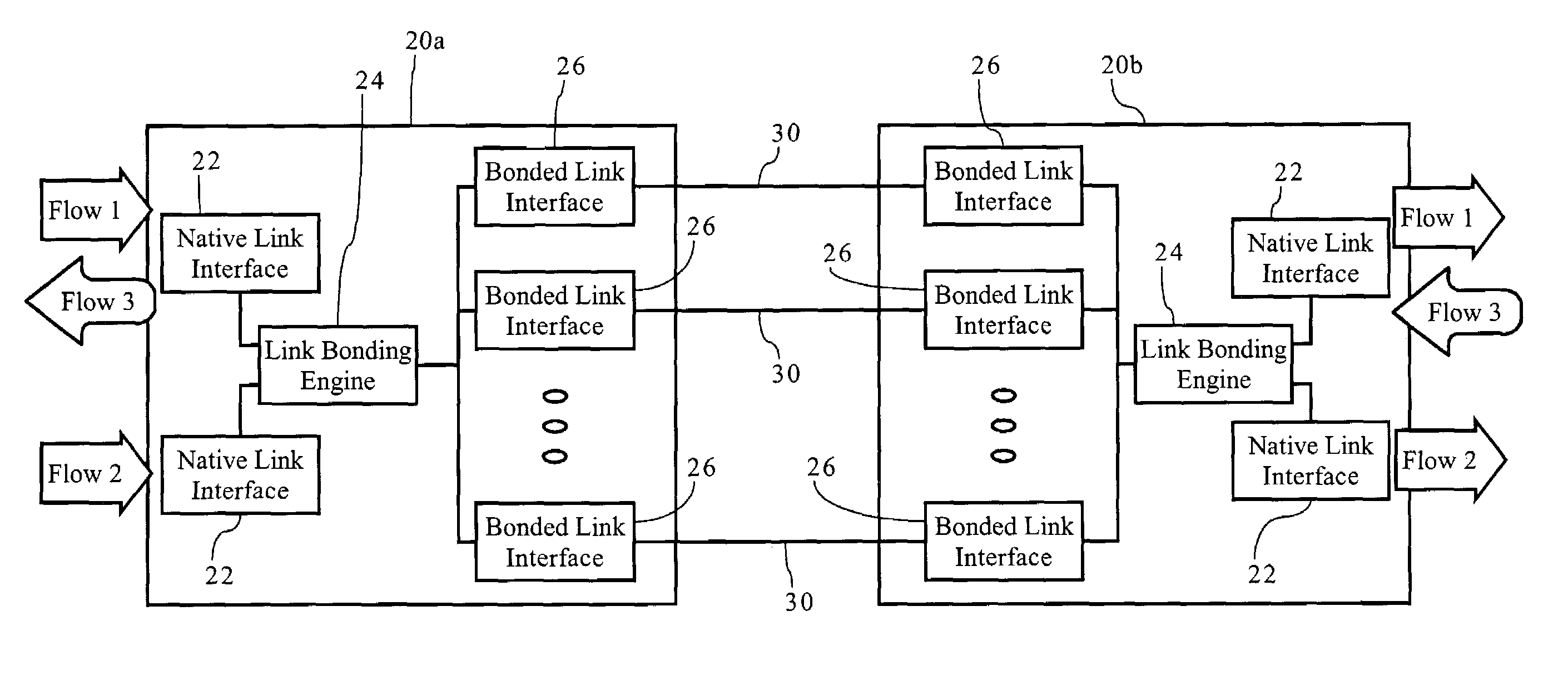
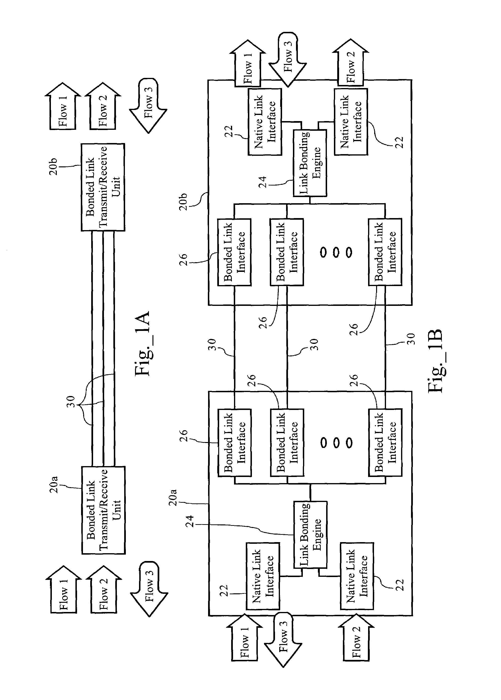
[0027]FIG. 1A illustrates operation of the communications path aggregation or bonding functionality according to one embodiment of the present invention configured to bond physical links into a single, higher bandwidth logical link. As FIG. 1 illustrates, a plurality of physical links 30 operably connect a first bonded link transmit / receive unit 20a to a second bonded link transmit / receive unit 20b. As discussed more fully below, bonded link transmit / receive unit 20a, in the transmit direction (e.g., flows 1 and 2), processes native flows and transmits them across one or more bonded links 30 to a second bonded link transmit / receive unit 20b, which reassembles the native flows for further transmission. As FIG. 1A illustrates, bonded link transmit / receive units 20a and 20b also operate in the reverse direction. In addition, as FIG. 1A illustrates, the link aggregation system transports native flows transparently across bonded links 30. In ...


PUM


Abstract

Methods, apparatuses and systems facilitating the aggregation or bonding of communications paths into a higher-bandwidth, logical communications path. Embodiments of the present invention can be applied to bond different physical links (e.g., xDSL over twisted pairs), different channels on the same physical line, or even different channels or frequencies in a wireless communications network. The present invention further provides methods, apparatuses and systems facilitating the re-sequencing of data flows transmitted across bonded communications paths. In one embodiment, the re-sequencing methodology of the present invention adapts to the transmission delays (both absolute and relative) across the bonded communications path.

Description

RELATED APPLICATION[0001]The present application is a continuation-in-part of U.S. application Ser. No. 10 / 202,108 filed Jul. 24, 2002, now U.S. Pat. No. 6,879,590, and entitled “Methods, Apparatuses and Systems Facilitating Aggregation of Physical Links into Logical Link,” claiming priority from U.S. Provisional Application Ser. No. 60 / 375,730 filed Apr. 26, 2002 and entitled “Methods, Apparatuses and Systems Facilitating Aggregation of Physical Links into Logical Link,” both of which are incorporated by reference herein for all purposes.FIELD OF THE INVENTION[0002]The present invention relates to telecommunications systems and communication link bonding technologies and, more particularly, to methods, apparatuses and systems facilitating the bonding of communications paths into a higher-bandwidth logical communications path.BACKGROUND OF THE INVENTION[0003]DS1 links, providing an access capacity of 1.5 Megabits per second (Mbps), dominate the existing access infrastructure. The ne...

Claims


Application Information

Patent Timeline
Patent Type & Authority Patents(United States)
IPC IPC(8): H04L12/28H04L12/56H04M11/06
CPCH04L45/00H04M11/062H04L45/245Y02B60/33Y02D30/50
Inventor PEDERSEN, SOREN BOSHILSHTUT, RADIMIRTHOM, DANNYSOLTANI, SINALOHANI, MANISH
Owner KLAMATH NETWORKS
Learn More