Control of operation conditions within fluidic systems

a fluidic system and operation condition technology, applied in the direction of fluid speed measurement, electrolysis, isotope separation, etc., can solve the problems of inability to readily access and control the reaction, and inability to control the reaction

Inactive Publication Date: 2005-10-27
CAPLIPER LIFE SCI INC
View PDF23 Cites 154 Cited by
  • Summary
  • Abstract
  • Description
  • Claims
  • Application Information

AI Technical Summary

Problems solved by technology

Similarly, the nature of the reaction vessels used in conventional technologies, while illustrating the advantages of microfluidic systems, also obviate some of the potential problems of microfluidic systems.
Similarly, the open-top nature of these vessels allows the evolution of other interfering components, which is not reasonably practicable in sealed microfluidic channels.
Further, because of their enclosed nature, one cannot readily access and control the reactions as they progress through the system.
In addition, the sealed nature of these systems can result in the accumulation of evolved gasses from the fluid reagents of a system, where such gases would dissipate into the atmosphere in conventional assay formats.

Method used


Image

  • Control of operation conditions within fluidic systems
  • Control of operation conditions within fluidic systems
  • Control of operation conditions within fluidic systems

Examples


Embodiment Construction

I. General

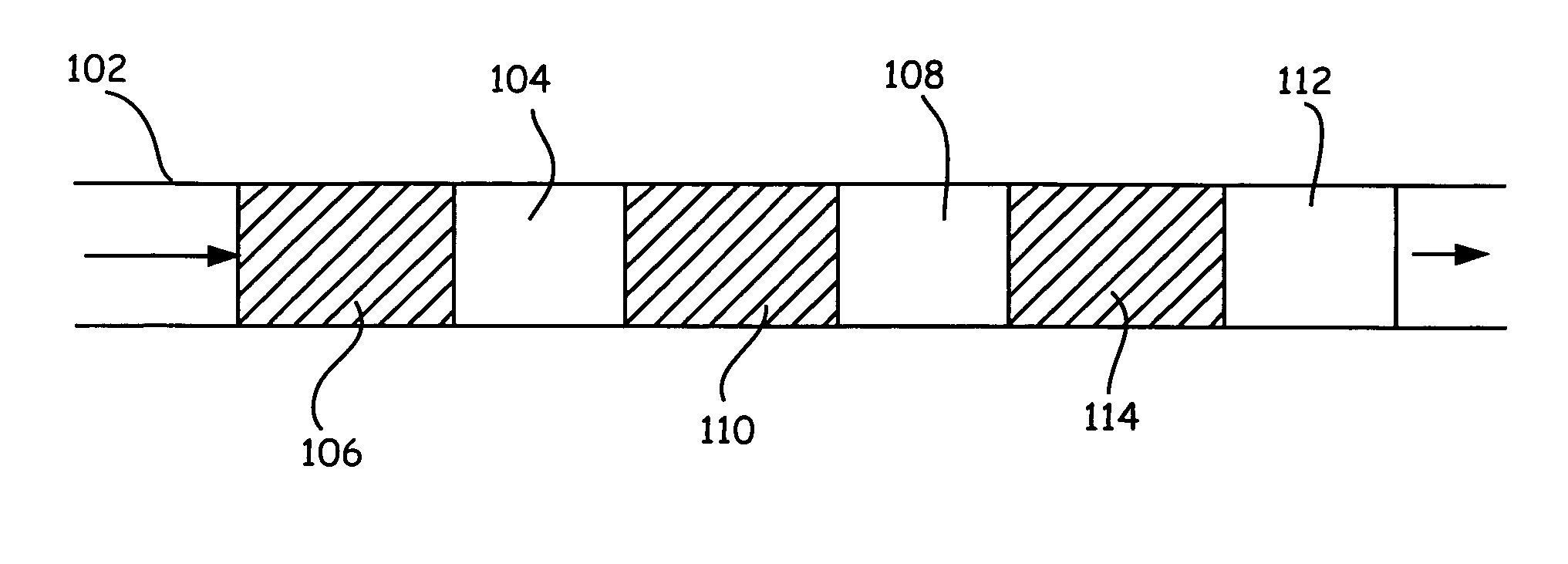
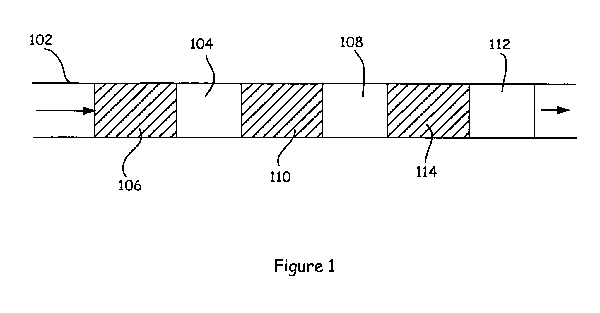
[0011] The present invention generally provides methods for optimizing the operation of microscale channel based systems through the use of environmental or operation control reagents within the fluids that are being transported through the capillary channels. In optionally preferred aspects of the invention, the environmental or operation control reagents are transported in fluid regions that are different from fluid regions that contain the reagents of interest for a given analysis, although such reagents may optionally be disposed within the fluid regions that contain the reagents of interest.

[0012] As used herein, the phrase “environmental control reagent” or “operation control reagent” refers to a reagent that typically is not involved directly in the reaction of interest, but instead modifies, controls or provides an indication of the state of the environment within a microscale channel in which a reaction of interest is taking place, so as to control that environme...


PUM

PropertyMeasurementUnit
temperaturesaaaaaaaaaa
temperatureaaaaaaaaaa

Abstract

Methods of controlling environmental conditions within a fluidic system, where such environmental conditions can affect the operation of the system in its desired function, and fluidic channels, devices and systems that are used in practicing these methods. Such methods are generally directed to environmental control fluids, the movement of such fluids through these systems, and the interaction of these fluids with other components of the system, e.g., other fluids or solid components of the system.

Description

CROSS-REFERENCE TO RELATED APPLICATIONS [0001] This application is a continuation of U.S. patent application Ser. No. 09 / 993,385, filed Nov. 14, 2001, which is a continuation-in-part of U.S. patent application Ser. No. 09 / 919,369, filed Jul. 31, 2001, which claims priority to Provisional Patent Application No. 60 / 223,072, filed Aug. 4, 2000. The full disclosure of each of these applications is incorporated herein by reference in its entirety for all purposes.BACKGROUND OF THE INVENTION [0002] Microfluidic systems have advanced to the point where they are beginning to supplant conventional technologies in biological, chemical and biochemical analyses. For example, routine separation based analyses, e.g., nucleic acid separations, protein sizing separations, and the like are now routinely performed in microfluidic systems, e.g., the Agilent 2100 Bioanalyzer and Caliper LabChip® systems. Similarly, high throughput analytical operations, e.g., pharmaceutical screening, high throughput g...

Claims


Application Information

Patent Timeline
Patent Type & Authority Applications(United States)
IPC IPC(8): B01L3/00B81B1/00G01N27/27G01N27/447G01N35/00G01N35/08G01N35/10
CPCB01L3/5027G01N2035/1034B01L3/502784B01L2200/0673B01L2200/0684B01L2200/141B01L2300/0816B01L2300/105B01L2300/14B01L2400/0415B01L2400/0487B01L2400/049B01L2400/084G01N27/44791G01N35/08G01N2035/00237B01L3/502746Y10T137/0324Y10T137/0391Y10T436/2575
Inventor PARCE, J. WALLACEYAO, YUNG-MAE M.MORRISSEY, DONALD J. JR.
Owner CAPLIPER LIFE SCI INC
Why Eureka
Try Eureka