Unlock instant, AI-driven research and patent intelligence for your innovation.
Analysis device and an analysis apparatus using the analysis device
Active Publication Date: 2009-10-01
PHC HLDG CORP
View PDF8 Cites 49 Cited by
Summary
Abstract
Description
Claims
Application Information
AI Technical Summary
This helps you quickly interpret patents by identifying the three key elements:
Problems solved by technology
Method used
Benefits of technology
Benefits of technology
[0028]According to the analysis device and the analysis apparatus of the present invention, the solid component or the high-concentration solid component solution which is obtained by performing the centrifugal separation can be transferred by a required amount. Further, the sample solution which remains when a part of the sample solution has been transferred can be prevented from flowing in afterward, thereby enhancing the measurement precision of the analysis device.
Problems solved by technology
Further, when only the solution component is transferred by the capillary tube having the siphon structure, the remaining solution again flows into the capillary tube with stopping of the rotation, and the solution in the capillary tube is again transferred by the next rotation, thereby adversely affecting the measurement precision due to variation in the solution amount or flow-in of the solid component into the capillary tube.
Method used
Image
Click on the blue label to locate the original text in one second.
Reading with bidirectional positioning of images and text.
Examples
embodiment 1
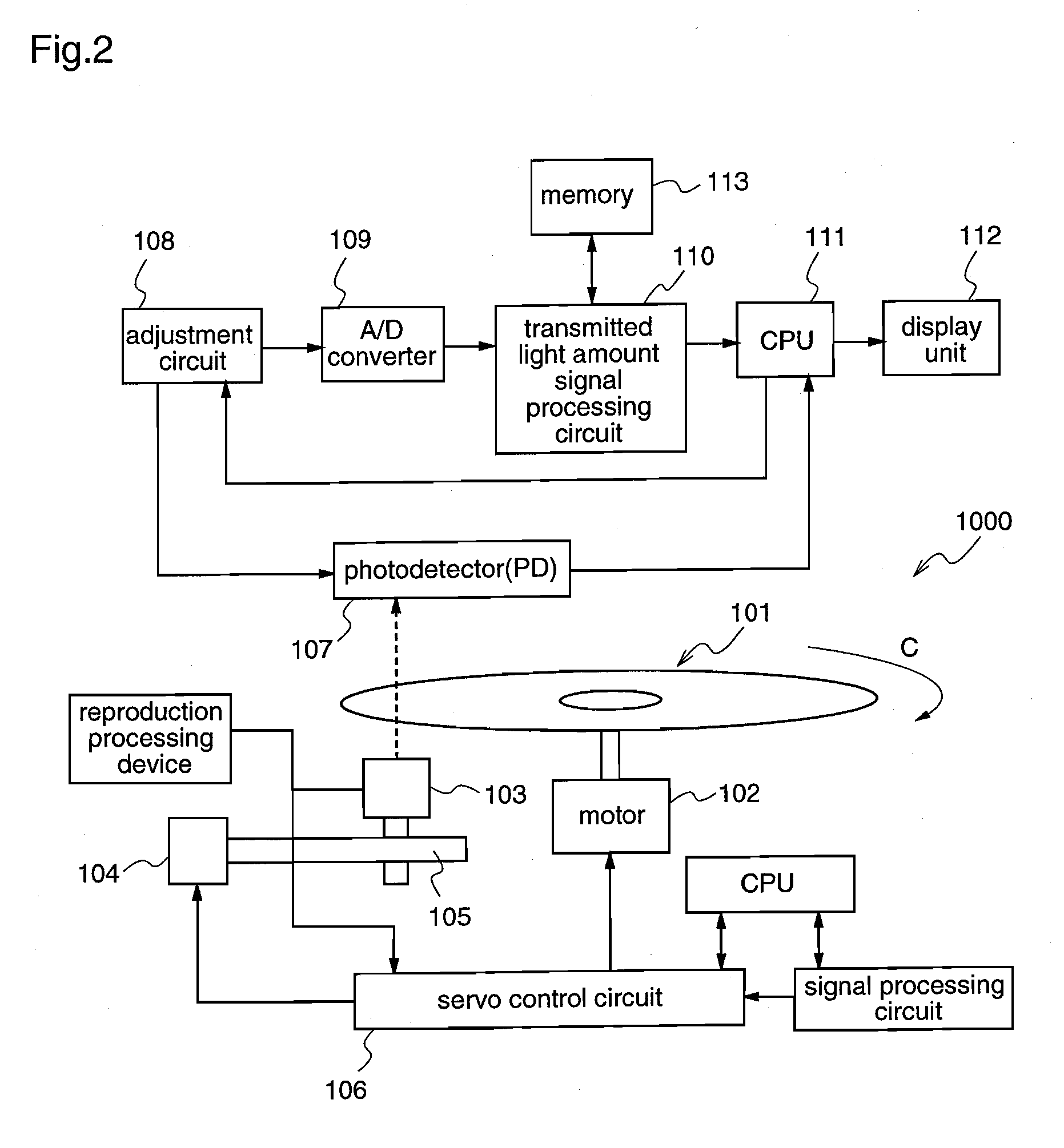
[0053]Hereinafter, an analysis device 101 according to a first embodiment corresponding to claims 1, 2, and 5 and an analysis apparatus 1000 using the analysis device 101 will be described with reference to FIGS. 1 to 5.
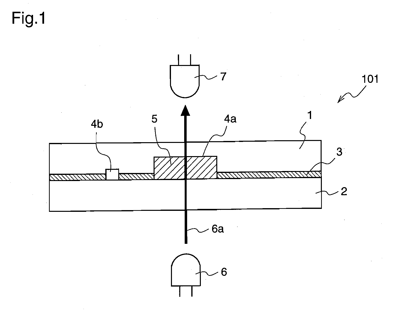
[0054]FIG. 1 is a schematic diagram illustrating the construction of the analysis device 101 according to the first embodiment of the present invention.
[0055]With reference to FIG. 1, the analysis device 101 comprises a substrate 1 having microchannels 4a and 4b, a flat substrate 2, and an adhesive layer 3 by which the both substrates are bonded together. Further, a reaction solution 5 is filled in the microchannel 4a among the microchannels which are formed by bonding the substrates 1 and 2 together.
[0056]The microchannels 4a and 4b on the substrate 1 are obtained by fabricating a concavo-convex microchannel pattern by injection molding. A sample solution to be analyzed is injected into the analysis device 101, and the sample solution can be transferred in the devic...
embodiment 2
[0091]Hereinafter, an analysis device 201 according to a second embodiment corresponding to claims 1, 3, and 5 and an analysis apparatus 1000 using the analysis device 201 will be described with reference to FIGS. 6 to 8.
[0092]The main construction of the analysis device 201 and the construction of the analysis apparatus 1000 on which the analysis device 201 is mounted are identical to those of the first embodiment, and therefore, repeated description is not necessary.
[0093]FIG. 6 is a plan view illustrating the structure of microchannels in the analysis device 201 of the second embodiment. FIGS. 7(a) and 7(b) are diagrams for explaining the injection and separation processes of the analysis device 201, and FIGS. 8(a), 8(b), and 8(c) are diagrams for explaining the measurement process of the analysis device 201 and the filling process of the measurement cell 28.
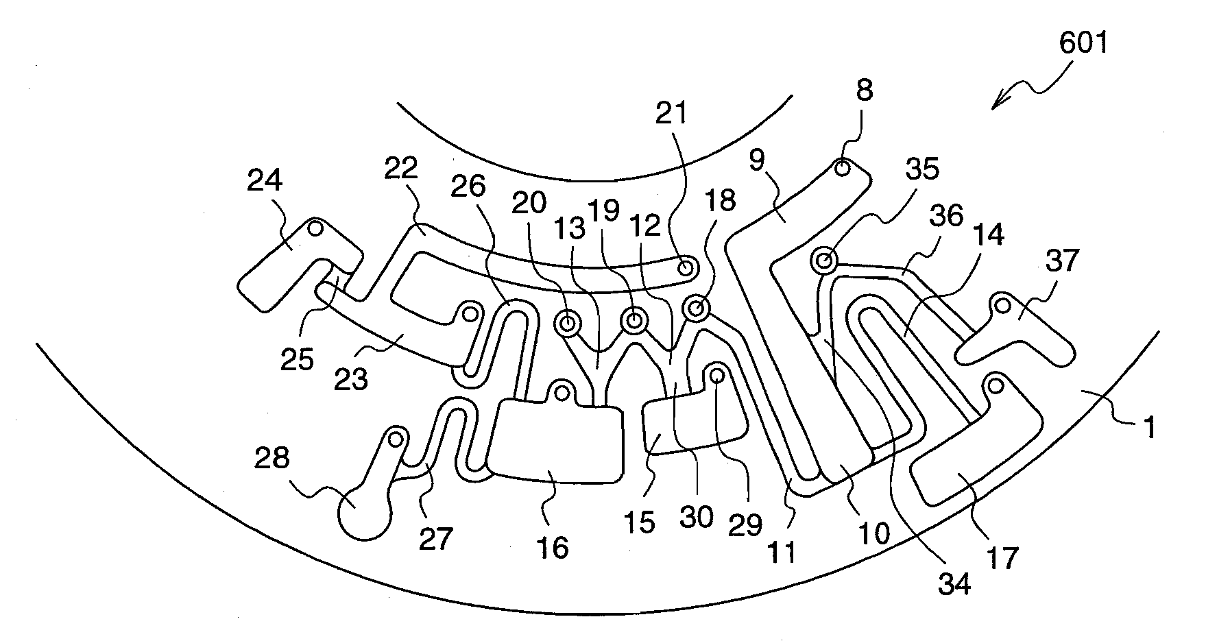
[0094]With reference to FIGS. 6, 7, and 8, the microchannel structure of the analysis device 201 according to the second em...
embodiment 3
[0114]Hereinafter, an analysis device 301 according to a third embodiment corresponding to claims 6, 7, 9, and 10 and an analysis apparatus 1000 using the analysis device 301 will be described with reference to FIGS. 9 to 11.
[0115]The main construction of the analysis device 301 and the construction of the analysis apparatus 1000 on which the analysis device 301 is mounted are identical to those of the first embodiment, and therefore, repeated description is not necessary.
[0116]FIG. 9 is a plan view illustrating a microchannel structure in the analysis device 301 of the third embodiment. FIGS. 10(a) and 10(b) are diagrams for explaining the injection / separation processes of the analysis device 301, and FIGS. 11(a) and 11(b) are diagrams for explaining the measurement process of the analysis device 301 and the filling process of the measurement cell 28.
[0117]With reference to FIG. 9, the microchannel structure of the analysis device 301 according to the third embodiment comprises a f...
PUM
Abstract
An analysis device comprises a separation chamber for separating a sample solution into a solution component and a solid component, a holding channel for holding a predetermined amount of the separated solid component, a mixing chamber connected to the holding channel, an overflow channel connected between the holding channel and the separation chamber, a sample overflow chamber into which the sample solution remaining in the separation chamber is discharged, and a joint channel connecting the separation chamber and the sample overflow chamber. After the separated solution component fills the overflow channel with priority by a capillary force, the separated solid component is transferred to the holding channel via the overflow channel, and a predetermined amount of the solid component is measured. The solid component in the holding channel is transferred to the mixing chamber by a centrifugal force, and simultaneously, the sample solution remaining in the separation chamber is discharged to the sample overflow chamber by the siphon effect of the joint channel.
Description
FIELD OF THE INVENTION[0001]The present invention relates to an analysis device for optically analyzing a biological fluid, and an analysis apparatus using the analysis device. To be specific, the invention relates to a method of collecting a solution component or a solid component in an analysis device which is used for component measurement for a biological fluid in an optical analysis apparatus, and more specifically, to a method of collecting a plasma component or a blood cell component in blood.BACKGROUND OF THE INVENTION[0002]Conventionally, as a method for optically analyzing a biological fluid, an analysis method using a microdevice having fluid channels has been known. A microdevice can control a fluid by using a rotation device, and it can perform measurement of a sample solution, separation of a solid component, and transfer / distribution of a separated fluid by utilizing a centrifugal force, and therefore, it can perform various kinds of biochemical analysis.[0003]As a de...
Claims
Application Information
Patent Timeline
Application Date:The date an application was filed.
Publication Date:The date a patent or application was officially published.
First Publication Date:The earliest publication date of a patent with the same application number.
Issue Date:Publication date of the patent grant document.
PCT Entry Date:The Entry date of PCT National Phase.
Estimated Expiry Date:The statutory expiry date of a patent right according to the Patent Law, and it is the longest term of protection that the patent right can achieve without the termination of the patent right due to other reasons(Term extension factor has been taken into account ).
Invalid Date:Actual expiry date is based on effective date or publication date of legal transaction data of invalid patent.

