Supercharge Your Innovation With Domain-Expert AI Agents!

Patient immobilization device

a technology for immobilizing devices and patients, applied in the field of patient immobilization devices, can solve the problems of affecting the comfort of patients, and affecting the comfort of patients, and achieve the effect of preventing the block from falling over

Inactive Publication Date: 2005-11-03
TOMCANY BRIAN +1
View PDF49 Cites 23 Cited by
  • Summary
  • Abstract
  • Description
  • Claims
  • Application Information

AI Technical Summary

Benefits of technology

[0016] In another aspect of the present invention, when the paddles are in a support position and are held against the head of a patient, such as with straps, the opposing friction surfaces cooperate to fix the lateral position of the paddles. Prior to securing the paddles around the patient's head, they snap into place when folded to the support position. The paddles slide along slots formed along the backboard and a snap structure on the paddle engages the slot when the paddle is folded to lock the paddle in the support position, thereby preventing it from falling over when positioned with respect to the patient's head.
[0018] In another aspect of the invention, a cushion is removably mounted in the recess in the backboard front side, between the paddles. The cushion provides comfort to the patient's head and has a contoured bottom surface. The recess containing the cushion includes drain holes formed in the floor of the recess and the contour of the cushion extends partially above the recessed floor to expose the drain holes to allow fluid to drain out of the recess.

Problems solved by technology

Although such systems have proven suitable for use with a backboard to immobilize a patient, they present other problems.
Repeated cleaning of the blocks may cause premature deterioration of the blocks and their covering or outer skin.
Another problem with such reusable blocks is that they are difficult to store when not in use.
Separation of key pieces of the patient immobilization equipment for the purpose of storage can often lead to lost or misplaced items.
Accident scenes are often chaotic environments involving multiple emergency medical service providers.
Therefore, any lost time involved in gathering up all the pieces necessary for head and neck support and patient immobilization is particularly undesirable.
Furthermore, because the blocks are separate pieces from the board, they often become lost or are mistakenly collected by other medical providers, such as at an accident scene or during equipment recollection at a medical facility.
During such recovery, one team or unit may inadvertently grab the equipment of another unit.
This essentially increases the overall cost of the equipment for an emergency service provider.
Furthermore, because such single-use devices often utilize adhesives for attachment to a backboard, repeated attachments require the removal and cleaning of the board proximate the adhesive.
Another drawback with disposal head immobilization devices is that they often use cardboard as their primary construction material.
Many patients and the public, in general, do not perceive cardboard as a particularly robust material as compared with other materials used to make emergency medical equipment, such as rigid plastic used to make backboards and cervical collars.
One prevalent cause of a dislodged intubation tube is movement, particularly head movement, which can occur when a patient is panicking or is having a seizure.

Method used


Image

  • Patient immobilization device
  • Patient immobilization device
  • Patient immobilization device

Examples


Embodiment Construction

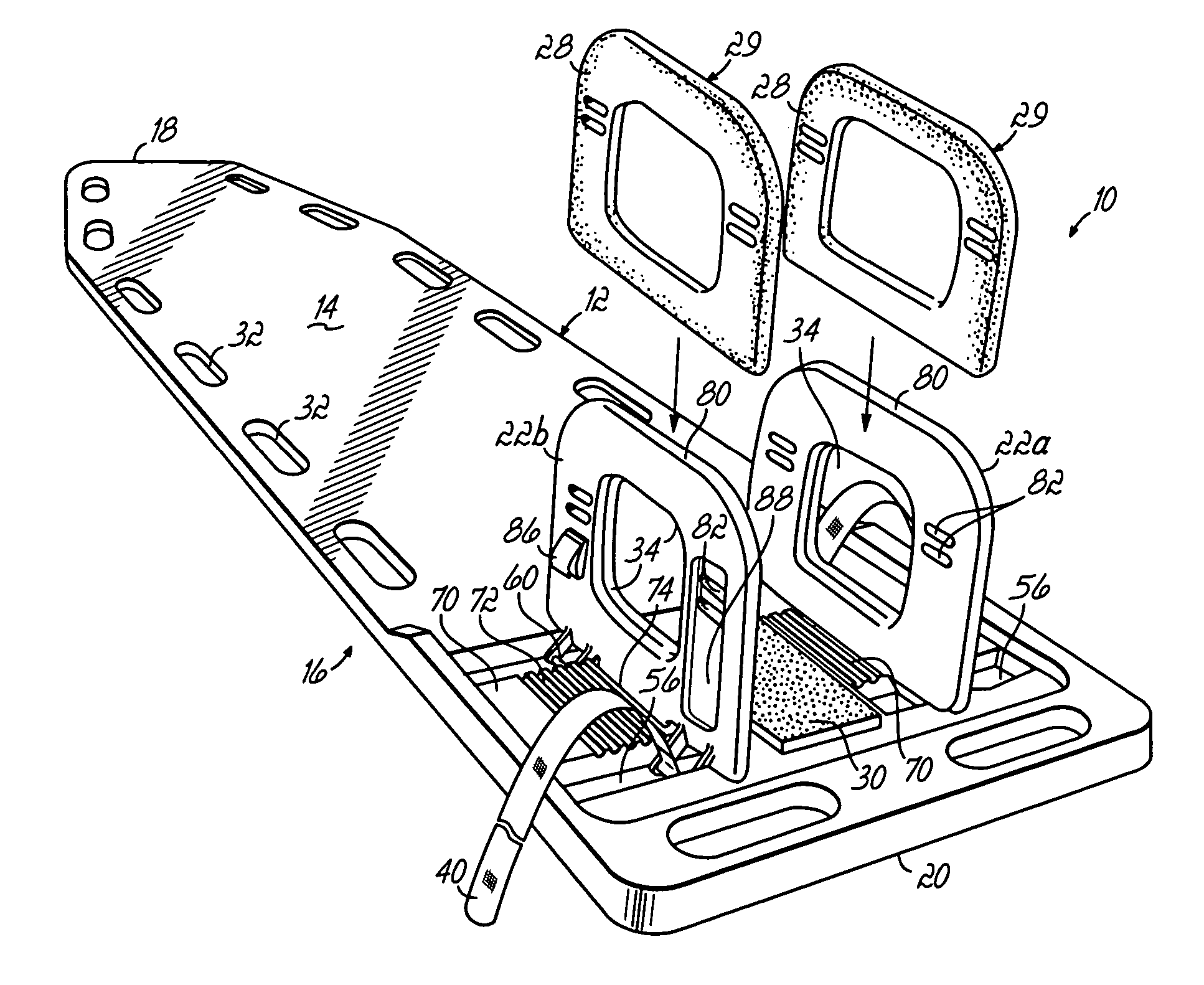
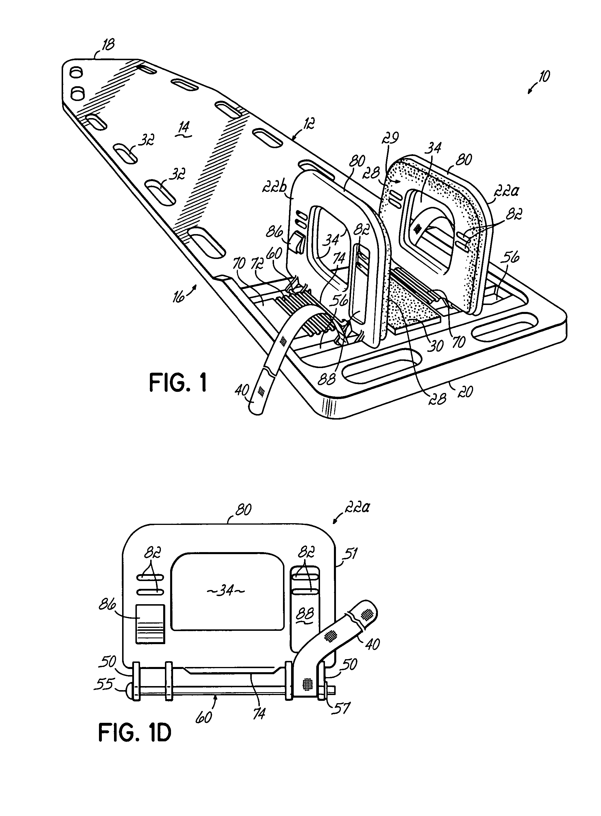
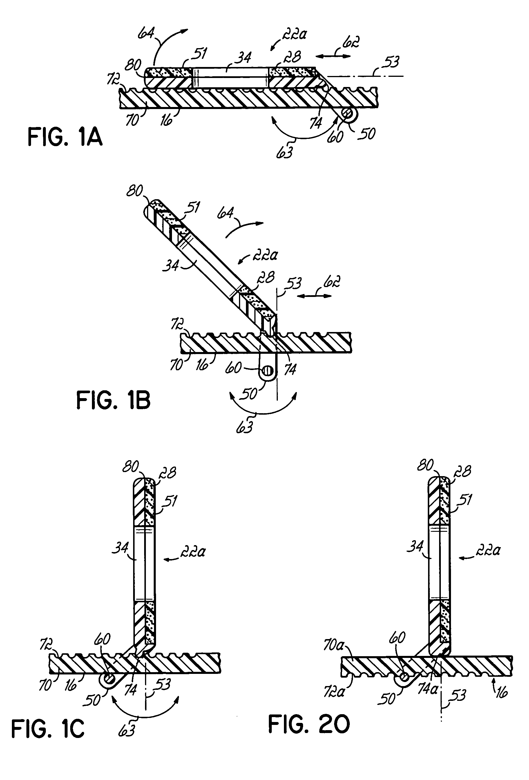
[0065] Referring to FIG. 1, a perspective view of a patient immobilization device 10 of the invention is illustrated. Generally, such a device comprises a backboard or backboard portion 12, having a top side or front side 14, and a bottom side or back side 16. In use, a patient would generally be placed on the front side 14, with their feet at the foot end 18 of the backboard and their head at the head end 20 of the backboard. For securing the head and neck of a patient, the invention utilizes a pair of opposing paddles 22a and 22b, which are slidably mounted on the backboard 12, and are configured, in a support position, to support the head and neck of a patient. Embodiments of the paddles 22a, 22b are illustrated in the support position in FIG. 1.

[0066] Referring to FIG. 2, the head 23 and neck 25 of the patient 26 are secured and immobilized between the paddles during use. The body of the patient 26 lies along the length of the backboard 12, and often is secured to the backboard...


PUM


Abstract

A patient immobilization device comprises a backboard having a front side and a back side, and a pair of opposing paddles slidably mounted on the backboard. The paddles are configured to move between a storage position and a support position, to support the head of a patient. Each paddle has a leg portion depending there from and extends through a respective slot formed in the backboard between the front and back and sides. A spanning portion of the paddle depends from the leg portion and engages the back side of the backboard to secure the paddle to the backboard. The spanning portion moves in a generally arcuate path between the storage and support positions.

Description

RELATED APPLICATIONS [0001] This application is a Continuation-In-Part application of U.S. patent application Ser. No. 10 / 335,523, filed Dec. 31, 2002 and entitled “Patient Immobilization Device,” which application claims priority to U.S. Provisional Application Ser. No. 60 / 359,622, filed Feb. 26, 2002, and entitled “Backboard with Head Immobilizer,” which applications are incorporated herein by reference in their entireties.FIELD OF THE INVENTION [0002] This invention relates generally to a patient immobilization device including a backboard and head immobilizer used to support and immobilize injured patients. BACKGROUND OF THE INVENTION [0003] In accidents involving apparent injury to the head, neck, and / or spine, the patient is immobilized for treatment and transport. Specifically, the head and cervical spine areas of the patient are routinely immobilized to prevent further injury during transport to a medical facility. For such immobilization, devices such as rigid backboards ar...

Claims


Application Information

Patent Timeline
Patent Type & Authority Applications(United States)
IPC IPC(8): A61F5/37A61G1/01A61G1/04A61G1/044
CPCA61F5/3707A61G1/044A61G1/04A61G1/01
Inventor TOMCANY, BRIANHELMSDERFER, JOHN A.
Owner TOMCANY BRIAN
Features
  • R&D
  • Intellectual Property
  • Life Sciences
  • Materials
  • Tech Scout
  • Unparalleled Data Quality
  • Higher Quality Content
  • 60% Fewer Hallucinations
Learn More