Scuba tank lock assembly

Active Publication Date: 2005-11-03
WHISENANT TERRIE
View PDF36 Cites 27 Cited by
  • Summary
  • Abstract
  • Description
  • Claims
  • Application Information

AI Technical Summary

Benefits of technology

[0020] In an alternative embodiment, the distal end of the attachment cable can include an aperture adapted to receive the shackle bar of a padlock. The padlock prevents the attachment cable from being withdrawn from the aperture, and allows the locking device to be secured to a fixed structure or another locking device using the attachment cable.
[0021] It is an objective of the invention to provide an inexpensive, durable, reliable, and portable means of locking scuba tanks.
[0022] It is another objective of the invention to provide a locking device

Problems solved by technology

Thus, even if older equipment is used it is meticulously maintained since any failure could result in injury or death.
For this reason, most any accessory used in diving is very expensive and, due to the portability of the profession, easily transported.
While many of the accessories can be hidden from the view of a potential thief, some of the accessories are impractical to conceal due to size, weight, space considerations or the inherent dangers associated with concealing some of the items.
For instance, scuba tanks are commonly left on the deck of a boat due to problems in storage.
Since scuba tanks are expensive and easily moved they make for easy prey by thieves

Method used


Image

  • Scuba tank lock assembly
  • Scuba tank lock assembly
  • Scuba tank lock assembly

Examples


Example

[0050] Although the invention will be described in terms of a specific embodiment, it will be readily apparent to those skilled in this art that various modifications, rearrangements, and substitutions can be made without departing from the spirit of the invention. The scope of the invention is defined by the claims appended hereto.

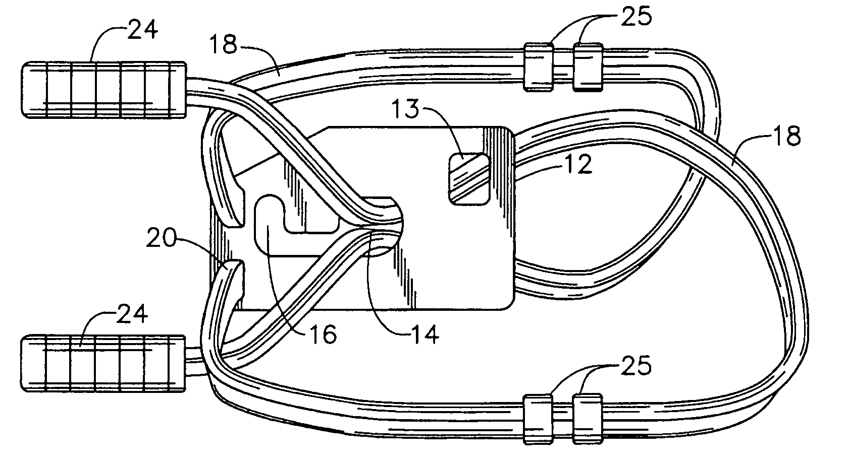
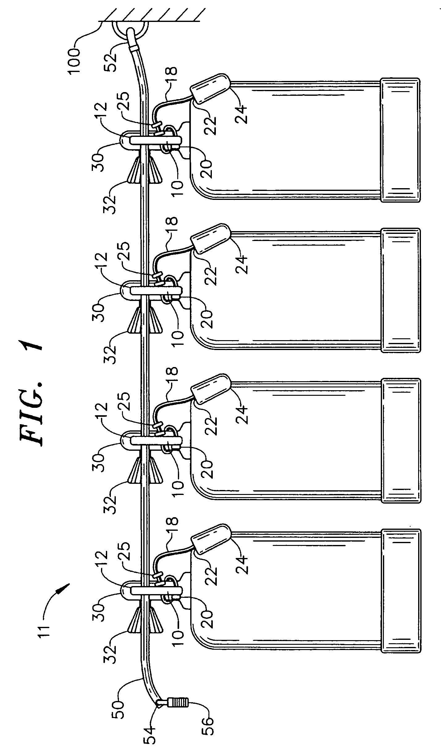
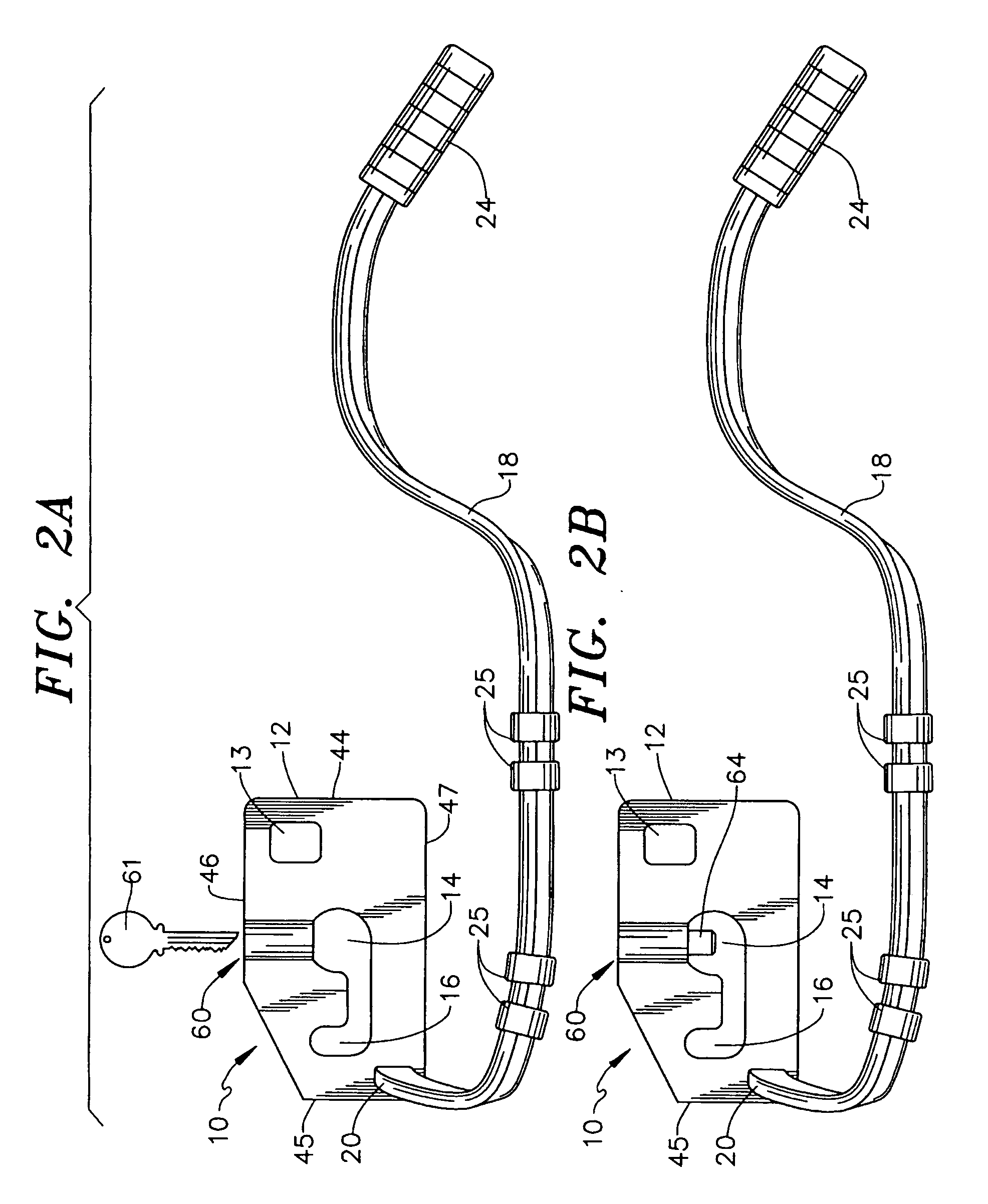
[0051] Now referring to FIG. 1, a locking device assembly 11 is depicted which secures multiple pieces of equipment to a fixed structure 100. The locking device assembly 11 includes a plurality of locking devices 10 secured by an elongated flexible securement means (cable lock 50) which is locked to a stationary structure. The locking device assembly 11 can be used to secure and lock any item (or items) having a suitable configuration. In FIG. 1, the locking device assembly 11 is shown as used with scuba tanks. The scuba tanks consist of cylinders housing compressed air, argon, helium, nitrogen or a mix of thereof. Scuba tanks are available in several st...


PUM


Abstract

A locking device comprises a locking plate having a first aperture to receive a cable lock, a second aperture having a slot extending therefrom, and a flat attachment cable having one end fixedly attached to the locking plate which is sized to be insertable into the second aperture for subsequent positioning in the slot. Cable crimps on the attachment cable have a width greater than the width of the slot. A locking means is provided which prevents movement of the cable crimps through the aperture when placed in a locked position. In use, the locking means is placed in an unlocked position, and the flat attachment cable is wrapped around an item to be locked and then inserted into the second aperture such that a cable crimp passes through the second aperture and the attachment cable is transversed for placement into the slot, and the locking means is then locked.

Description

RELATED APPLICATIONS [0001] This invention is a continuation-in-part of application Ser. No. 11 / 007,532 filed Dec. 7, 2004, which is a continuation-in-part of application Ser. No. 10 / 666,186 filed Sep. 17, 2003, now U.S. Pat. No. 6,829,916, the contents of which are incorporated herein by reference.FIELD OF THE INVENTION [0002] The invention relates to locking devices, and more particularly to a locking device for securing sporting equipment and the like to a fixed stationary object in either single or multiple configurations. BACKGROUND OF THE INVENTION [0003] Recreational and professional scuba divers require numerous accessories for underwater exploring and / or work. The accessories include air tanks, weights, buoyancy compensators, computers, wet suits, float balls / flags, and so forth. All such accessories are necessary for a safe dive and typically consist of the latest in technology. Thus, even if older equipment is used it is meticulously maintained since any failure could res...

Claims


Application Information

Patent Timeline
IPC IPC(8): B63C11/02E05B73/00
CPCB63C11/02E05B73/0005B63C2011/024B63C2011/023Y10T70/409Y10T70/5009
Inventor DEVECKI, RONALD W.
Owner WHISENANT TERRIE
Why Eureka
Try Eureka