Plastic single-piece tube

Inactive Publication Date: 2005-11-03
BORMIOLI ROCCO & FIGLIO
View PDF4 Cites 9 Cited by
  • Summary
  • Abstract
  • Description
  • Claims
  • Application Information

AI Technical Summary

Benefits of technology

[0022] The upper part 1c of the tube 1 and the cap 3 are slightly thicker than the trunco-conical body of the tube 1. In a brief tract of tube 1 between the upper part of the tube and the remaining part of the tube 1, there are thin internal ribs 5 which are arranged in a radial direction. In particular, in the illustrated tube, four ribs are present and located equidistant from each other. This particular conformation of the upper part 1c of the tube 1 enables a greater consistency to be obtained for that part of the tube, and facilitates the exit of the product from the tube 1. This greater consistency does not however constitute an obstacle to the squeezing of the tube 1 to cause the product to exit, which in fact does happen with some known tubes, such as for example those tubes made using the technique of welding the upper part of the tube to an extruded tube body. In this kind of realisation, the welding zone becomes a little stiffer, which makes the tube difficult to squeeze. The internal ribs 5 also have a further important function in relation to the stocking of the tubes, as will be better explained herein below.
[0023] The tube of the invention, which is made together with the cap in a single moulding process, confers high productivity on the moulds. Its shape also makes the tubes easy to stack, as show

Problems solved by technology

As with all objects whose unit cost is relatively low but which are produced in large numbers, the main problem the producers face is how to limit costs and production times, by limiting the number of separate parts ne

Method used


Image

  • Plastic single-piece tube
  • Plastic single-piece tube

Examples


Example

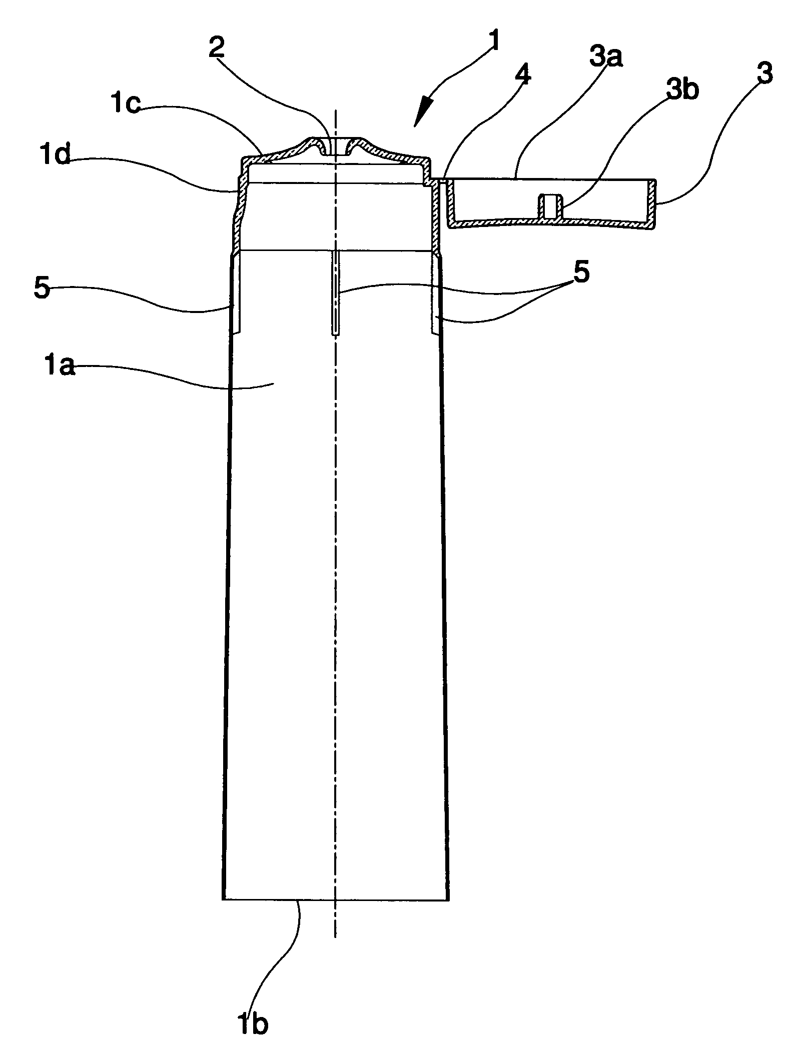
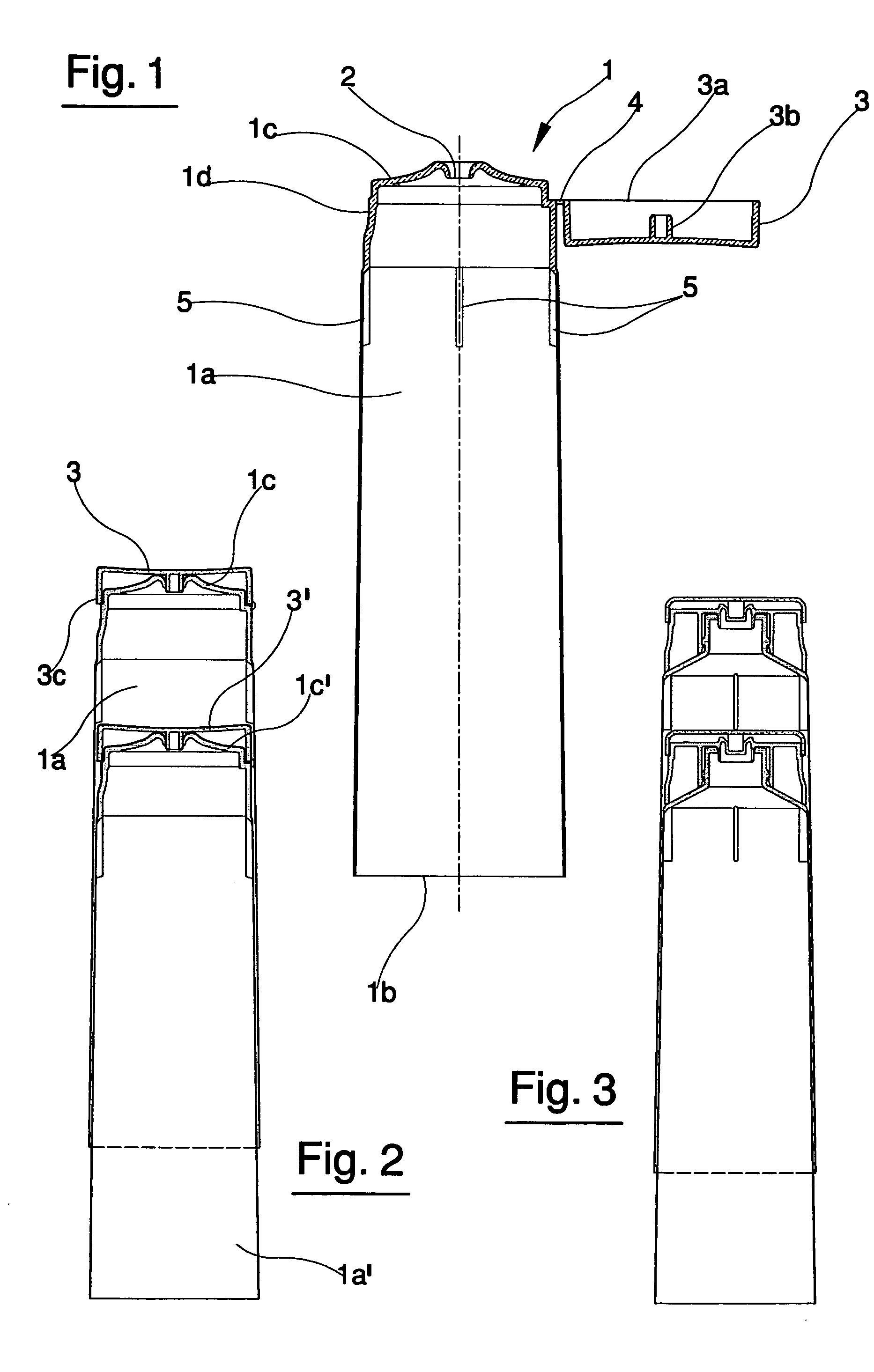
[0012]FIG. 1 is a section in vertical elevation of a first embodiment of the tube of the invention;

[0013]FIG. 2 is a reduced-scale view of a section of two tubes as in FIG. 1, one inserted in another;

[0014]FIG. 3 shows a section of two tubes, slightly differently made with respect to those illustrated in FIGS. 1 and 2, one inserted in another.

[0015] In FIGS. 1 and 2, 1 denotes a single-piece tube made of plastic. The plastic material used can be of known type and is suitable for injection-moulding.

[0016] The tube comprises a trunco-conical body 1a which exhibits a coning angle of between 1° and 4° and which has an open lower part 1b. In filling plants this open lower part 1b is used to fill the tube. The lower part 1b of the tube can be closed after the introduction of the fluid product, for example by hot-welding.

[0017] The tube is further provided with an upper part 1c, which in this embodiment is an integral part of the tube, in which a passage is provided for exit of the pro...


PUM


Abstract

The tube, in particular for containing fluid products such as creams and cosmetic products in general, includes: a trunco-conical body (1a) having a lower part (1b) which is open for introduction of the product, and can be closed after the introduction; and also an upper part (1c) affording a passage for exit of the product from the tube. A cap (3) can be applied on the upper part (1c) of the tube for closing the passage and is connected to the upper part (1c) of the tube by a hinge element (4). The tube, the cap (3) and the hinge element (4) are all made in a single piece obtained by injection moulding.

Description

TECHNICAL FIELD [0001] The invention relates to a single-piece tube made of plastic. For some time plastic tubes have been used in substitution for metal tubes, especially in the technical field of tubes destined to contain fluid products such as creams or in general cosmetic products. BACKGROUND ART [0002] The tubes in this field usually include a central body having a lower part which is open for the introduction of the product, and which is closed after the filling operation. The upper part of the central body has a passage for the exit of the product from the tube. These tubes are made by either welding the upperpart to a drawn cylindrical tube, or by directly moulding the whole tube by injection of plastic material in a special die. The present invention relates in particular to the latter type of tube. [0003] The finished tube is sent to producers of the product destined to fill the tube by introduction into the open lower part, whereupon the bottom of the tube is welded, the ...

Claims


Application Information

Patent Timeline
IPC IPC(8): B65D35/08B65D35/44B65D47/08
CPCB65D35/08B65D47/0838B65D35/44
Inventor MORINI, EMILIO
Owner BORMIOLI ROCCO & FIGLIO
Why Eureka
Try Eureka