Model 3D construction application program interface

a program interface and 3d construction technology, applied in the field of computer graphics, can solve the problems of affecting the visual appearance of the frame, the current model of preparing the frame using bitmaps requires too much data processing to keep up with the refresh rate of hardware, and the limit of the traditional model of accessing graphics on the computer system

Inactive Publication Date: 2005-11-03
MICROSOFT TECH LICENSING LLC
View PDF8 Cites 39 Cited by
  • Summary
  • Abstract
  • Description
  • Claims
  • Application Information

AI Technical Summary

Benefits of technology

[0006] The above and other problems are solved by a computer data structure applied to computer program objects to construct a tree hierarchy to render a three-dimensional (3D) scene of 3D models. The root object in the tree hierarchy collects the objects for the 3D scene. A group object in the tree hierarchy collects other group obj

Problems solved by technology

The limits of the traditional model of accessing graphics on computer systems are being reached, in part because memory and bus speeds have not kept up with the advancements in main processors and/or graphics processors.
In general, the current model for preparing a frame using bitmaps requires too much data processing to keep up with the hardware refresh rate when complex graphics effects are desired.
As a result, when complex graphics effects are attempted with conventional graphics models, in

Method used


Image

  • Model 3D construction application program interface
  • Model 3D construction application program interface
  • Model 3D construction application program interface

Examples


Embodiment Construction

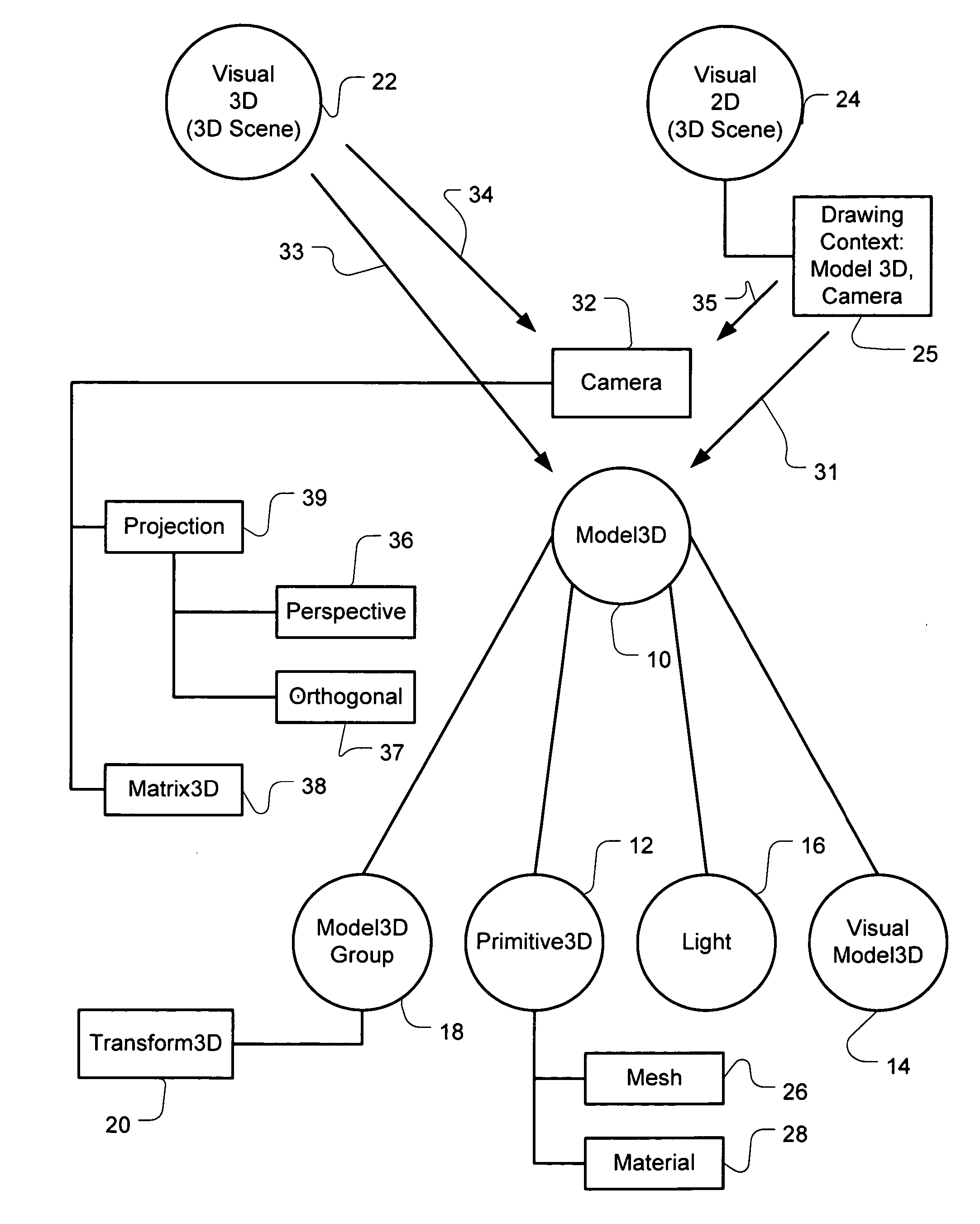
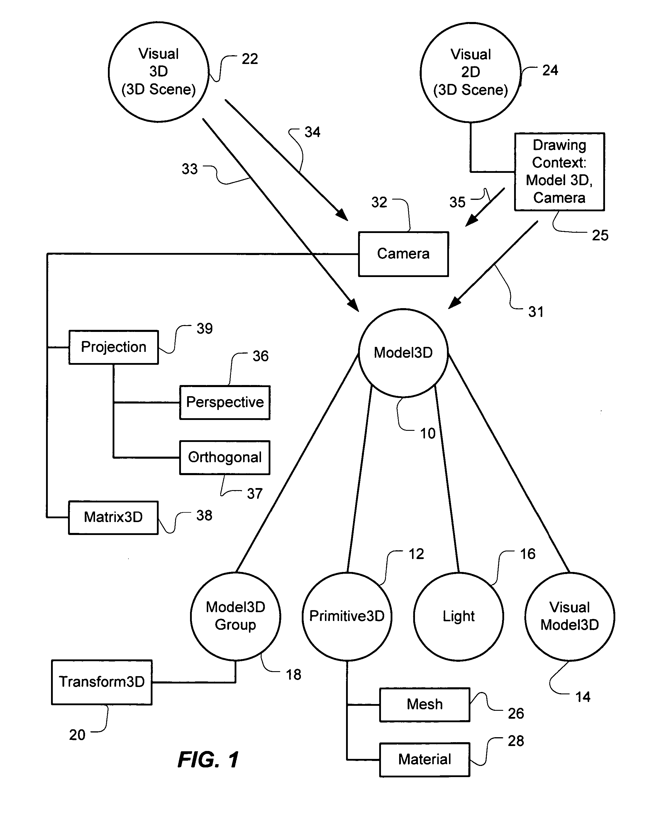
[0020]FIG. 1 illustrates an architecture of computer program objects for implementing Model 3D API in accordance with one embodiment of the invention. The Model3D object 10 is a root or abstract object. There are four possible model 3D objects that are children related to root object. The three objects, Primitive3D object 12, Visual Model3D object 14, and Light object 16 are leaf objects in this architecture. Model3D group object 20 is a collecting node in the tree for leaf objects or other group objects and also contains Transform3D object 18. Transform 3D object has a hierarchy of transform objects associated with it.

[0021] Primitive 3D object contains a mesh information 26 and material information 28 that also may reference or point to hierarchies of objects to assist the definition of the 3D model being drawn by Primitive3D object 12. Visual Model3D object 14 defines a 2D image for incorporation into the 3D scene. Light object 16 defines the illumination for the 3D scene and ha...


PUM


Abstract

An application program interface may be used to construct a three-dimensional (3D) scene of 3D models defined by model 3D objects. The interface has one or more group objects and one or more leaf objects. The group objects contain or collect other group objects and/or leaf objects. The leaf objects may be drawing objects or an illumination object. The group objects may have transform operations to transform objects collected in their group. The drawing objects define instructions to draw 3D models of the 3D scene or instructions to draw 2D images on the 3D models. The illumination object defines the light type and direction illuminating the 3D models in the 3D scene. A method processes a tree hierarchy of computer program objects constructed with objects of the application program interface. The method traverses branches of a 3D scene tree hierarchy of objects to process group objects and leaf objects. The method detects whether the next unprocessed object is a group object of a leaf object. If it is a leaf object, the method detects whether the leaf object is a light object or a drawing 3D object. If the leaf object is a light object, the illumination of the 3D scene is set. If a drawing 3D object is detected, a 3D model is drawn as illuminated by the illumination. The method may also performs a group operation on the group of objects collected by a group object.

Description

CROSS REFERENCE TO RELATED APPLICATION [0001] The present application is related to U.S. patent application Ser. No. ______, entitled VISUAL AND SCENE GRAPH INTERFACE, filed ______, U.S. patent application Ser. No. ______ entitled DECLARATIVE MECHANISM FOR DEFINING A HIERARCHY OF OBJECTS, filed ______, U.S. patent application Ser. No. ______ entitled INTEGRATION OF THREE DIMENSIONAL SCENE HIERARCHY INTO TWO-DIMENSIONAL COMPOSITING SYSTEM, filed ______, and U.S. patent application Ser. No. ______, entitled TRANSLATING USER INPUT THROUGH TWO-DIMENSIONAL IMAGES INTO THREE-DIMENSIONAL SCENE, filed ______. All of these applications assigned to the Assignee of the present invention and hereby incorporated by reference in their entirety.TECHNICAL FIELD [0002] The invention relates generally to the field of computer graphics. More particularly, the invention relates to application program interfaces for three dimensional scene graphics. BACKGROUND OF THE INVENTION [0003] The limits of the t...

Claims


Application Information

Patent Timeline
IPC IPC(8): G06F9/44G06F19/00G06TG06T13/00G06T15/00G06T15/70G06T17/00
CPCG06T17/005G06T15/00
Inventor SCHECHTER, GREG D.SWEDBERG, GREGORY D.BEDA, JOSEPH S.SMITH, ADAM M.
Owner MICROSOFT TECH LICENSING LLC
Why Eureka
Try Eureka