Rear view mirror with built-in camera

a technology of rear view mirror and built-in camera, which is applied in the field of rear view mirror with built-in camera, can solve the problems of inability to see or difficult to see the infrared light source of the infrared projection device positioned inside the transparent cover, and achieve the effects of suppressing the emission of visible light, simple structure and simple construction

Inactive Publication Date: 2005-11-03
STANLEY ELECTRIC CO LTD
View PDF6 Cites 50 Cited by
  • Summary
  • Abstract
  • Description
  • Claims
  • Application Information

AI Technical Summary

Benefits of technology

[0022] In accordance with an aspect of the invention, the above and other problems are taken into consideration to provide a rear view mirror with built-in camera that is equipped with an infrared projection device that has appropriate light distribution characteristics, and uses a simple structure to suppress the emission of visible light from the infrared projection device, thereby making the device substantially or totally invisible when viewed from an external position. This rear view mirror with built-in camera can enable the poor visibility blind spot near the front corner of a vehicle to be monitored using a CCD camera, causing little or no distractions for the drivers of oncoming vehicles. Furthermore, in accordance with another aspect of the invention, a rear view mirror with built-in camera can be provided in which the infrared projection device itself is of a simple construction.

Problems solved by technology

Furthermore, the transparent cover can transmit the infrared light from the infrared light source of the infrared projection device, but may not transmit visible light.
Consequently, if the transparent cover is viewed from an external position, the infrared light source of the infrared projection device positioned inside the transparent cover can be difficult to see or cannot be seen at all.

Method used


Image

  • Rear view mirror with built-in camera
  • Rear view mirror with built-in camera
  • Rear view mirror with built-in camera

Examples


Embodiment Construction

[0071] The following is a detailed description of various embodiments of the invention, with reference to FIG. 1 through FIG. 5. The embodiments described below represent specific examples of various forms of the invention, and therefore include a variety of technical features. The scope of the invention should not be considered to be limited to these embodiments.

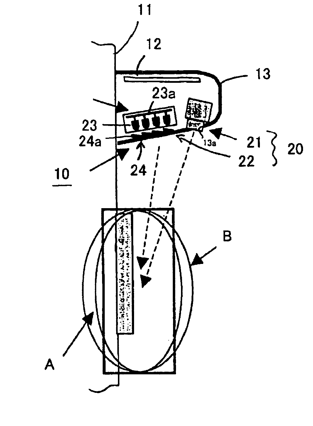
[0072]FIG. 1 shows an embodiment of a rear view mirror with built-in camera made in accordance with the principles of the invention.

[0073] In FIG. 1, a rear view mirror 10 with built-in camera is a so-called door mirror that can be positioned, for example, on the left-hand passenger side of a vehicle 11. The rear view mirror 10 can include a mirror housing 13 that contains a mirror 12 for visually checking behind the vehicle, and a camera module 20 that is built into the lower region of the mirror housing 13. In this embodiment, the definitions of left and right are based on the direction of movement of the vehicle 11. Fu...


PUM


Abstract

A housing device, such as rear view mirror, with built-in camera can include an infrared projection device with an infrared light source for irradiating infrared light onto an image capture region for the camera. The camera can display a sensitivity to visible light and infrared light, and can be built into the mirror housing which is mounted to a vehicle and contains a mirror used for visual checking purposes. The infrared projection device can include a light transmission cover. The cover can be positioned in an infrared irradiation direction of the infrared light source, can be formed from a material that is impenetrable to visible light and transmits only infrared light, and can be attached to the mirror housing in an integral manner.

Description

[0001] This application claims the priorities benefit under 35 U.S.C. § 119 of Japanese Patent Application Nos. 2004-135532 filed on Apr. 30, 2004 and 2004-185516 filed on Jun. 23, 2004, which are hereby incorporated by reference. BACKGROUND OF THE INVENTION [0002] 1. Field of the Invention [0003] The invention relates to a rear view mirror with built-in camera, equipped with an infrared projection device. More specifically, the invention relates to a rear view mirror with built-in camera including a surveillance camera for monitoring the vicinity of the front wheel, and an infrared projection device that is capable of irradiating infrared light at the monitored region. [0004] 2. Description of the Related Art [0005] It is well known that a blind spot exists near the front corners of vehicles, particularly in the vicinity of the front wheels. One known means for dealing with this blind spot involves attaching small CCD cameras to the housings of the door mirrors, enabling the sides ...

Claims


Application Information

Patent Timeline
Patent Type & Authority Applications(United States)
IPC IPC(8): B60R1/12H04N7/18
CPCB60R1/12H04N7/183B60R2001/1253B60R1/1207
Inventor TAKANO, TEIICHIROKAWAGUCHI, YOSHIFUMINISHIYAMA, JUNJIOKAMURA, TAKEAKI
Owner STANLEY ELECTRIC CO LTD
Why Eureka
Try Eureka